Blog updates are posted oldest to newest.
TC-2 Tube Checker
Heathkit Catalog - 1958Kit Price...............$29.50
Assembled: N/A
Sold from 1953-1959, the TC-2 appears to have had the longest production run of any tuber checker Heathkit came out with. This was my Dad's second or third kit he ever built. He was a teenager then and having the tube chart roll dated 12-1-56 puts this unit at least 14 years before the SB-303 he purchased and repaired. I have a 6EW6 tube in the IM-13 and did not see it in the list on this tube chart. I located a copy of a tube chart, in book form by Eico, that is dated 1-1-78. Since the Eico Model 625 was the same as Heathkit's TC-2, this reference can be used to facilitate tubes released up to 1977 with one caveat. You have to convert Eico's numbered levers to Heathkit's lettered ones. I'll try to find an original Heathkit updated tube chart to use on the roll but it is pretty cool to see an original dated from the 1950's. More info to come as I am able to locate it. Also, check out Jeff Tranter's video on this unit and other vintage equipment here.

Excerpt from the assembly manual, Page 4:
The Heathkit model TC-2 Tube Checker was expressly designed for checking tubes encountered in everyday radio and TV service work. Its is capable of providing and overall quality test, witll indicate shorted elements, open elements and filament continuity. It will check 4, 5, 65 and 7 pin, large, regular and miniature, octal, loctal, Hyrtron, 9 pin miniature series tubes and pilot lamps. Separate tests for the the oscillator section of converter tubes have been provided. A blank socket is arranged on the panel to facilitate modification for checking newly added tube types as protection against obsolescence.
The roll chart contains all necessary data for the checking of currently used tubes. Because of the constantly growing list of tubes, it was decided to eliminate tubes classified as seldom-used or obsolete, in an effort to hold down the physical length of the roll chart. The information for various settings of the tubes in this particular classification is supplied on a separate sheet. The Heath Company periodically revises the roll chart in order to provide the latest test information. Announcement of new chart availability is usually made in Heathkit Flyer advertising and replacement charts can be obtained for a nominal charge of fifty cents ($0.50).
As you have just read, this test gear is an emission type tester (not mutual conductance) and the tests are limited. This does not mean it isn't useful. In fact most, if not all, of the tube testers in grocery stores, drug stores and hardware stores were of this type. It might have been to sell more tubes because of a weak filament. Click here for a summary of the differences in tube testing.
I remember as a little kid going to Safeway with my Dad to test some tubes he pulled out of the GR-180 TV on a General Electric stand-up tester with storage cabinet and glass door. This must have been before he got the TC-2. I would get to pull the slide switch down to TEST and watch the needle on the meter. If a tube was weak or bad, a new one was purchased from the stock in the storage compartment below.
The TC-2 I now have has been in a basement flood event but had not been submerged. From appearances it seems to have just been somewhat wet through absorption as the laminate of the box is barely separating along the bottom edge about 1/4" wide. The rear Masonite panel has a water mark indicating it might have laid on something wet or soaked up water from the lower left corner. I don't remember if it was laying in a box or standing on a lower shelf, but it did soak up some water.


It looks to have had a tough time in storage. The meter cover is cracked and scratched, it's dirty and has mouse droppings stuck to it. Can't wait to open it up!
Updates to this project coming soon!
73!
_________________________________________
September 4, 2017
I got started on the TC-2 tonight and see how much it will need to restore. I don't have any extra parts to begin actual work on the checker unless I happen to already have them for another project. I'll need to keep an inventory of the parts used so I can replace them for those other projects waiting in the wings.Below are the pics I took prior to disassembly. I'll comment for each photo.
 |
| An initial look at the unit. Notice some of dirt collected mostly around the sockets. As you can see here, I have all the knobs. It is complete from the front side. |
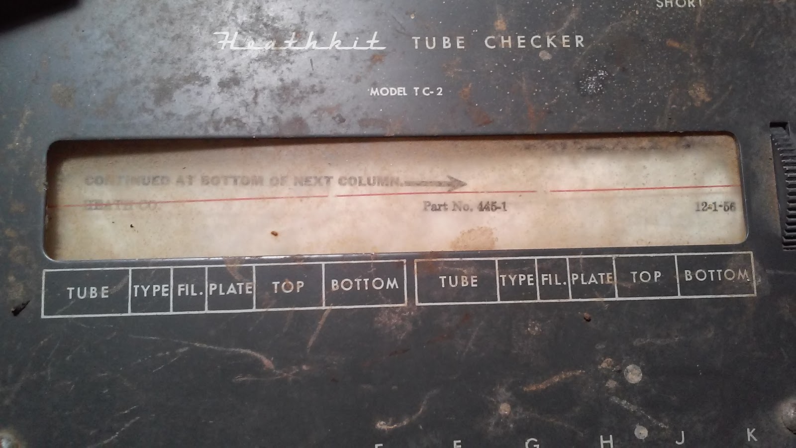 |
| If you look closely, you can see the tube chart part number is 445-1 in the center and the 12-1-56 date on the right. The paper is in amazingly good shape so I doubt this unit was submerged in water. Various marks that look like scratches can bee seen in this photo too. |
 |
| A closer look at the cracked meter cover and it's waaaay off initial position setting. |
 |
| Yeah. those are turds. The sockets aren't cracked but as you can see, the rubber grommet for the test clip has hardened a long time ago and broken apart. Not that it matters but moving the lead caused more to break up. The rubber insulation is also hard and cracked. It will be replaced with a synthetic insulated wire this time around. |
 |
| No turds but still dirty. Not sure what the speckled stuff if though. Might be the metal plate underneath as the paint is deteriorating. No cracked sockets either. This is encouraging. Will find out if the momentary slide switch still works after I take it apart and clear the corrosion that must be in there. |
 |
| Ah. More scratches it seems and a rusty screw that is one of four that hold the tube chart frame in place. The screws for the switches in the lettered row should clean up good with a Dremel and a wire wheel...in a vise. ;-) |
 |
| More dirt but no apparent scratches on this side. |
 |
| Really dirty chart cover. Hope this can be cleaned up and reused. If not, will be looking for a place that can duplicate it. I might use material that is 1/16th inch thick (1.5-ish mm) instead of the clear film. I can put spacers beneath the chart frame if it is a problem later. The #47 bulbs underneath will be very warm and I suspect the film did not trap the heat as much as a thicker plastic would. I will consider LEDs in this respect. |
 |
| It isn't apparent as to why the duct tape is on this knob. I found the pointer is not part of the knob but rather fitted to it. I think the tape was holding the pointer in place to show where it was really set to. |
 |
| Opening it up, again. This time on video. The old webcam imagery was so bad it wasn't acceptable for use. I will warn you that I am no cameraman so I apologize for any poor work here. |
 | |
| A little closer inspection. |
 |
| So this little capacitor sweated. Or is it a capacitor? Once I find the schematic, I'll know but for now it looks like a capacitor, tastes like a capacitor, smells like a capacitor, and explodes like a capacitor so it must be a capacitor. Guess I don't need that schematic to tell what it was, just what it should be. ;-) In all seriousness, old equipment like this can be made worse by the stupidly or arrogantly ignorant just by plugging it in and turning it on to "see if it lights up." So many restorable pieces of equipment just get abused or trashed and tossed by those arrogantly ignorant SOBs who have no business having possession of such artifacts. Sorry. That's a sore subject with me and it makes me smoke thinking about it. >-( Moving on now. |
 |
| And here it is. The infamous Selenium rectifier. Also known as a metal rectifier, these were used for a long time to convert AC to DC. This was the alternative to the vacuum tube and gas discharge type diode. The manufacturers knew these would go bad sitting on a shelf brand new and unused. One of the biggest advantages these had over their tube counterparts though were their instant-on capability. Unlike tube diodes which had higher voltage drops and longer start up times, the metal rectifier also had a higher efficiency than tubes. However, like I mentioned earlier, they had a limited life span even if unused. If you replace this with a 1N4007, you will have to insert a resistor of suitable wattage to recreate the voltage drop since the rest of the circuit was designed with that voltage drop. Here's a write up I came across about doing just that in other devices. This link will open the article on the author's site. Replacing Selenium Rectifiers by W3HWJ - Rick Bonkowski. Want to know more about the Selenium rectifier? Click here. |
 |
| An overall shot after removal of the tube chart and related parts. Pretty clean inside. Nary a sign of spiders in this one. |
 |
| And here's the face plate after an initial cleaning. What I thought were bad scratches were mostly dirt trails. The speckled splatter by the short circuit lamp is actually gold paint. Not sure how that got there. But with some more cotton swabs and window cleaner I should have it looking a little better. Getting the paint splatter off will be a challenge though. |
73 for now!
________________________________
June 26, 2017
I shot some video with an old 2MP auto focus web cam I found in my junk box of the first look. I'm not able to compress it below 136MB right now so I can't upload it. The video isn't great anyway and barely meets the old NTSC 320 standards but I wanted to try this type of thing out. It wasn't long and doesn't get close in detail but what I did find was a perfectly restorable piece of electronic history. This project will have to wait a bit since it will need some extensive cleaning and rework.________________________________
September 3, 2017
I've decided to go ahead with this project as I need it more than the IT-28 Capacitor Tester. Having this in operation will be better than not having anything at all. It's better than just plugging in a tube of unknown condition and hoping it doesn't light up a transformer. Be sure to return in a week or so as I will begin an operable restoration on this unit._________________________________________
September 19, 2017
Getting back to work on the TC-2 tonight I decided I would go through all of the original wiring. My Dad built the kit sometime in the late 1950's. The tube chart is dated the aforementioned 12-1-56 so I believe he built it before 1965, the year I was born. Tube radios and B&W televisions were common fare and his interest in electronics was quite strong. A conversation we had about these pieces of equipment brought up when he built certain units. His first was an antenna tuner. I believe this may have been built not long after. The tube chart was never updated and he couldn't remember when the this one was built. No problem. I have it and will restore it to operation. My dedication to vintage electronics is because of what I grew up with. My interest in electronics came from my Dad. God Bless Dad.It would seem imprudent to just replace the few resistors and lone capacitor with a quick fix. Since this is the earliest of kits I have my Dad built, I want to make sure time hadn't taken a harsh toll on it. Solder joints were viewed under a magnifying glass and several appeared good. Several others not so good. A little bit of green coloring showed on a couple of connections. I found one broken or cold joint on the 5-pin socket, pin 1 as viewed from the rear. The brown wire from the harness was able to rotate easily in the solder joint. So I decided then to go through every wire, every joint and replace only what was necessary. If it is in good shape then I would leave it. This also made me realize I needed more colored solid-core wire.
After evaluating some of the other challenges faced in bringing it back to operation I decided it would be a good idea to remove the transformer with the filament voltage selector switch. The switch is located underneath the transformer due to space constraints and has many of the wires from the transformer attached.
I'll wager the cabinet might have been deeper if there were more than one transformer to offer all the voltages. None of the voltage settings are done with resistor networks. They are all driven from a multi-tap transformer. I found his original assembly manual, complete with check marks and some of my own, "pen testing" marks on the back of the Pictorial 2 fold out. Ah the memories...ahem, and so I fired up the soldering iron to begin removing the transformer and filament switch as a unit.
Let me tell you about vintage rosin. Even well ventilated as my workbench is there is no escape from the past released in the smoke to bring memories of childhood flooding forth through the rosin vapors where it sends chills through the spine and the mind tingling with excitement of discovery along the journey.
 | |
| Left to right rear: "Bad/?/Good" meter, original manual, B&K 1570A Oscilloscope (screen covered). Middle: Transformer with filament rotary switch, tub-o-parts, and tools. Front: Rear of TC-2 main panel. |
With time and effort, much of the original solder will be wicked off the joints instead of re-flowing them as I restore it. I'm using the Kester "44" solder as I do on all my projects which has done me quite well over the years.
That's it for now.
73!
______________________________
September 20, 2017
I spent several hours overnight wrestling with the thought of undoing my Dad's original work he did nearly 60 years ago that built this piece of equipment. I do like keeping things original, when it works. Noting three cold solder joints where two had loose wires, and large amounts of solder on the joints, I went to bed to sleep on it. After a somewhat restless night, I got up this morning and watched a couple of episodes of SG-1 Season 6 on Hulu to lose myself in something unrelated. Halfway through episode 5: Nightwalkers, I decided to disassemble the test gear completely and rebuild it anew.You see, my Dad was a teenager when he built his first kit, an antenna tuner. I don't know where the TC-2 kit comes in terms of the number of assembled kits he did but I admire the work he did on it. I see some of the same mistakes I made in my early kit and project work when I was a teen so I naturally would want to "fix it". As I grew up, I learned from him I shouldn't settle for mediocrity or take it to heart just because it may be easier than working a little harder to get what I want. Instead, I should do the best I can. As much as I want his original work to function and do what his efforts achieved back in the day right now, I want to do my best in bringing it back up to operational use the best way I know how. All without shortcuts that, even if it were to preserve his work, might result in an unacceptable compromise. All I can say now is, Thanks Dad. You've taught me a lot and I'm trying to do my best with it.
Here are some pics of the disassembly.


With that said, here's a beginning photo of my TC-2 kit handed down to me by my Dad.

Some of the components are in sub-assemblies like the transformer and configuration switch bank. The tube sockets will be cleaned thoroughly, the rotary and potentiometer will be tested and cleaned as well as the lamps. New grommets will be used as will new colored 18ga hookup wire. This is a departure from the Heathkit's 20 AWG wire supplied with the kit. 20 gauge wire did work but I believe Heathkit used it because it was cheaper than 18 gauge and was adequate to the task. I'd like to take it to the next step and increase the safety margin while reducing any losses in the wire.
First I'd like to clean up the face plate but how to go about it without damaging the paint or the graphics. I've tried window cleaner and a cotton swab with CRC QD Electronic cleaner to no avail. I'm going to check out Goo-Gone and see if it is safe(r?) on painted surfaces. I know Goof-Off is a stripper so that's out. Maybe some Simple Green cleaner might work. Will have to check that out too. I just don't want the metal to corrode and blister the paint away.
73
___________________________
October 12, 2017
Just wanted to make a short entry tonight on the project. Been busy with PC builds and got another 21 waiting on me so this project isn't getting the attention I was expecting to give it. Sorry 'bout that.I think I have a way to clean the tube sockets that will produce good results. I got the idea from

October 15, 2017
Taking a break from PC building to work on the TC-2 a little. I wanted to get the tube sockets cleaned up since the Brasso, GooGone and CRC QD Electronic Cleaner routine worked pretty good. Not shiny new but much better looking now. | |
| Sockets clockwise from lower left: Blank Spare - U4A - U5A - Octal - Loctal - U6A U7B w/pilot lamp test socket - B9A in an Octal size base - "Hytron 5 Pin" - U7A |
What puzzled me was the Hytron 5 pin socket. That is what the manual calls it but it clearly has a 6th pin in the center. I think this is an oversight which happens. I wasn't able to locate any history on this socket, just a bunch of ebay references to tubes. Of course nobody selling Hytron tubes has a picture of the bottom of the tube(s) to see the pattern nor were there any measurements. I couldn't even find any reference in Wikipedia to Hytron. So for now, I'll just put it back into the tester as it was originally intended.
Now that all the sockets have been cleaned, I needed to reinstall the leaf springs back into the large tube sockets.


That's it for tonight. Drop by in a few days.
73!
___________________________
October 16, 2017
Probably should have said come back in a couple of shifts! LoL! So I got a PC built and wanted to get working on the TC-2 again tonight. I pulled the wavy rings from their storage tub (formerly a butter tub) and cleaned them off. Now, I've not had the (dis)pleasure of using these but I understand why Heathkit opted for them. It makes for a clean looking panel without through hole screws to hold the sockets. Personally I like the see the hardware but I'm not going to change this kit to suit that pleasure. Instead, I will grunt, pinch and maybe curse once trying to get the ring on. Getting it off was easy. Pry up the end and lift in a circle around the socket until it pops loose. Putting it on is somewhat more laborious due to the fact the socket wants to shift in the hole and settle with one edge of the panel sitting where the wavy ring is supposed to. One socket had been like that since original assembly due to the difficulty in getting the ring on without shifting. My solution to a misbehaving socket was to put a plastic cap underneath the socket allowing the pressure from the weight of the panel and my pressing down on the ring to keep it in place.In attempting to video this action, my camera mount broke and did not have a way to hold the camera and install the wavy ring. So now that the cursing phase is over, these pics will have to do and I can continue with socket installation.
 |
| So here is the kit by Dad built as a teen, once again in kit form. |
 |
| Ah yes, plenty of room and padding for the panel. Oh look! Dad's original manual! This is going to be a fun build! |
 |
| A 1 5/8ths inch diameter plastic bottle cap from an herbal supplement works nicely. |
 |
| Place the cap right-side up as shown. |
 |
| Place socket through hole in the correct orientation and let it sit on the cap. (Not all the scratch marks are mine.) I wasn't able to keep the wavy ring in place for a partial install shot as it kept slipping off. |
 |
| So I had to take a picture of Heathkit's visual on how the wavy ring is installed. |
 |
| With all of the sockets in place, I can move on to the power switch and test switch. |
Tune in again for more progress.
73!
____________________________________
October 20, 2017
Greetings! I did a little work on the power and test switches. The power switch was a bit noisy and didn't make a very good connection. Sometimes it would show more than 10 ohms on the meter. Any resistance in the power switch isn't good. Below are a few pics showing my remedy. |
| The power switch is a SPST slide type switch. Very simple in construction. |
 |
| After desoldering and removing wire fragments I bent the tabs holding the phenolic board in place. Careful bending by slowly lifting each tab up enough to clear the board. |
 |
| Lifting the board off the frame reveals the two contacts, contactor shoe and slider. Beneath the contactor shoe is a copper leaf spring to hold it snug against the contacts. |
 |
| Cleaning was done with CRC QD Electronic Cleaner and cotton swabs with the shoe in place. Holding the shoe with a toothpick will keep it in place while rubbing it with the cotton swab soaked in cleaner. Silver polish or Brasso may also be used for the tougher oxidation and dirt but this switch only seemed to be slightly dirty. The contacts were given the same treatment but with Brasso on a cotton swab to polish them. This will help make the two metal surfaces grind less. |
 |
| Removing the slider leaves just the frame. Simple! |
 |
| On the other side of the slider (actuator?) there was a spring shim to aid in smooth operation. This helps keep the plastic from wearing down and becoming sloppy. |
 |
| Completed cleaning shim and frame. Ready to reassemble. |
 |
| Slider in place the leaf spring/contactor is ready to be installed. |
 |
| To help in preventing oxidation and lower friction, I used a very small dab of dielectric grease on the contactor. It will protect the metal from humidity and slow corrosion/oxidation. |
73!
___________________________________
October 22, 2017
Took a break from PC building this afternoon after church so I could make a little more progress. I'll start with the TEST switch I mentioned in my last posting. |
| Similar in design to the power switch but with two sets of contactors. |
 |
| What's behind contactor number 2? Yep. Just a spring to hold it snug against it's contacting pads. The straight slot was probably already machined or molded into the slider. The holes for the contactors were put in to make the switch perform a double function. |
The board containing the contact pads is actually a fiber board. Have to be carefull with these as they can tear, not break, if not handled properly. Cleaning them with the Dremel then Brasso got them shiny new again. Assembly of the switch was completed and the test could be performed.
It is interesting to note that it didn't matter which way the contact board went back into the housing. It functions like it's supposed to either way. I like these kinds of designs because it reduces assembly line errors through simplification. Now that the switch has tested good, it was installed according to step 2 of page 7 in the manual. I list step numbers according to the number of steps on that particular page rather than from the beginning of the manual since none of the steps are numbered. It's easier to count the steps or check marks for an individual page that way.
Beyond these two switches, there aren't any more of this type. Two rotaries, two potentiometers, and lever switches are all the make up the controls for the TC-2.
I did spend time in using the Dremel to clean the screw heads. Putting in dull or rusted screws may give the unit an antique look but I like using the original parts in clean and either bright or polished condition to signify a level of completion to the restorative efforts.
While assembling the TC-2 "Re-Kit" I have been penciling in my own check marks at the completion of each step next to the ones my Dad made when he built it. I did look ahead and discover there aren't any check marks beyond a certain point. I understand why and I can imagine that after that point, the rest was intuitive and steps were superfluous.
So on to the next piece. The manual calls for the 200 ohm potentiometer for the plate voltage control to be installed at location Y. I used the VTVM (IM-13) to see any variance in operation. First, the total resistance of the winding was checked. It checked out good at a hair above 200 ohms. The DMM showed 202 ohms. The VTVM showed a major jump in resistance near the end of the pot's travel then drop back to just above 200 ohms. With some really slow movement of the control I was able to catch 395 ohms on the DMM. Not good. Not good at all. I'm not using the VTVM so much to read the resistance now but to see any inconsistencies the DMM misses. The VTVM is infinitely variable whereas the DMM updates every second and can miss those jumps or drops in value.
The tabs were straightened and the shell was removed to reveal a wire-wound potentiometer. A very tiny wire winding. So, Brasso or CRC electronic cleaner? I did both. First, CRC, to get any mess stripped away like flowed rosin residues or caked up grime since many of these used some kind of grease lube for the shaft bushing. Sure enough, there had been some on the contact area where the VTVM picked up the anomaly. Some had also been resting on the contactor of the rotary piece. A swab with just a touch of Brasso on it to clean and polish the winding, another blast of CRC and a touch of Labelle 106 to help smooth out the action. I didn't think the shaft needed to be pulled from the housing so I shot some RS tuner cleaner with lubricant down inside the housing and rotated the shaft until it freed up a tad. Another shot and some more exercising of the control shaft to make sure it would not bind up from any buildup breaking loose. It was good to go so back together it went.
I skipped the 14 pole rotary switch for position AA since it is still attached to the transformer. I'm not sure if I"ll disconnect it as the solder joints are good. The problem is testing the switch with it connected to the transformer. I might be able to determine connectivity through the windings but I may have to desolder it for that very reason.
I went to the next step and pulled the 4 position rotary out of the parts cup. It had burnt rosin on it and I didn't get all the solder off of two of the contacts when I removed the wiring. This kept one of the contacts spread open for that position when the silver conductor was to slide between them. Removing the solder fixed that problem. Now having cleaned the rotaries in the VTVM, I know how difficult it is to get a good soaking with a cleaning spray. DeoxIT would do better than CRC but I think it's too caustic and would use the CRC anyway to clean any DeoxIT left behind in the nooks and crannies that won't dry right away. So out came the wire wheel. I had to do it on the VTVM and just a light pass is all that is needed. Putting the switch in between positions let me get to the parts covered by the contacts. A blast of CRC to clean the debris from the piece and it was ready to lube.
Again, the RS tuner cleaner with lube was shot onto the rotary shaft and rotated it through its positions several times to work it into the bushing. Once it did free up some more I used the 106 to grease the position-keeping spring. With that done, it was ready to install in position CC. Check off step 5 on page 7.
And to complete today's work, the 200 ohm, 25 watt potentiometer is to be installed in position DD. But first, check and clean.
 | |
| Partial disassembly. The ceramic body containing the wire-wound resistance wire, rotator with contactor block and the locator ring used to center and hold the switch in place when mounted to a panel. Since Heathkit did not use this for that reason, an extra nut was to be placed on the underside to make up the spacing difference. It would have been easier to flatten out the tab but some things are best left to originality. |
 |
| The shaft have some pretty deep grooving from the setscrew over the years. These grooves left raised ridges the bushing could not get past. Thought a diamond finger nail file would have been the better choice, I didn't have one and opted for the stone bit on the Dremel. It took a little more metal off that I liked and the bushing came off easily. |
 | ||
| I used the wire brush in the Dremel on this face of the bushing then cleaned the whole piece with Brasso. It came out clean and the operation smooth after Labelle 106 was used to lubricate the bushing and wavy wing that presses against this face. |
 |
| A vigorous use of the wire wheel on the ground shaft did a good job of smoothing out the rough finish where the knob attaches to the shaft. After centering the control, I ground an index flat so the screw had some kind of point it could leverage against. |
 |
| Part Number 11-14: 200Ω 25W Ceramic Potentiometer. The 140741 looks to be a serial number, a date code of 14 July, 1941, or the original manufacturer part number. Heathkit could certainly have continued purchasing surplus parts and had their number stamped on it then or after they ordered it manufactured elsewhere. Can anyone confirm? |
 |
| Ready for installation. |
Just like on the VTVM, I used the Dremel on all of the flat washers and nuts that hold these controls in place. I have new replacements but where I can use these original parts, I'm happy to clean and re-use them. They polish up well and it helps to brighten up the look, even though they will be hidden underneath the knobs. About those knobs....
73!
__________________________________
October 26, 2017
Good evening. Just a quick update tonight. I have decided to scan the panel for reference purposes and have removed the sockets, controls and switches for that purpose. Might as well do it now before I begin the wiring. My scanner can't handle this large an item so I'm going to take it to a print shop. I do miss the old photographic scanner I used with my Amiga 2000. It took great scans as the longer the exposure, the better the detail. Pass-scanning has to be perfect in the one pass to get an image.I hope it can be of help if I need to replicate it in the future or if someone else can create a silkscreen from the graphic. I'm also hoping to get a few scanned images in hi-res color, grayscale as well as B&W to catch the graphics. Painting a solid color is easy. Recreating the graphics in silkscreen? That's hard. Might be easier to get rubber stamps for each control label made and have an auto body shop do the border in pinstriping.
I'll post a sample image or two once I get the files.
73!
__________________________________
October 27
As promised, I got a chance to get the panel scanned. Here's the grayscale image below. |
| Not a bad panel to be sure. Not mint either but rarely are any of them. |
I have three images. Color, Grayscale and B&W that cost less than $1.75. I believe the color image is a tad bit green since the scanner used fluorescent lighting instead of white light (6000K).
You can see a few of the imperfections from exposed aluminum caused by corrosion. I've heard the Gibbs Brand can stop the corrosion. I have no idea what it will do to the paint other than strip it. Unless I have a way to recreate the graphics on the panel, I'm going to leave it alone.
So now I can rest knowing I have a backup of the panel. Now it's time to put the sockets, switches, and controls in to begin wiring it up. Let's start this re-kit!
73!
________________________________
November 1, 2017
It's about 0500Z and I just finished the first stage of wiring the TC-2. I'll say this first and foremost: If you think you need 18AWG wire, think again. 20AWG is what came with the unit and 20AWG will do just fine. The caveat to using 18AWG 600V wire is the small solder lugs on the 9 m=pin miniature socket. You really cannot get two 18AWG wires into the hole of the lug for the daisy-chaining of the sockets. It's the only one I haven't been able to do it with. So I fell back and re-used the original 15" eight conductor cable my Dad used in the kit.The cable was actually four feet long to start with when he opened the box to build it. Two pieces, a 15 inch (38.1cm) and a 12 inch (30.5cm) were cut and prepped. I wasn't going to use either as I thought the gauge of wire used was 18AWG. Nope. Nada. Zip. 20AWG. So I reworked the 15 inch (38.1cm) piece and was pleasantly surprised to find there was more than enough to cut the ends, re-strip and solder into place. The rest of the unit will be wired with the 18AWG.
 |
| So here I am with the large diagram with the other one hanging on my left, out of view. With assembly manual and lots of parts, this re-kit is going pretty good. |
 |
| Here's the original 15 inch (38.5cm) length of 8 wire cable. A little rework, pulling the wires to straighten them out and cut off any excess to make it just right. At this point I hadn't yet realized how crowded those four sockets on the left were going to get. |
So begins the cutting of the "short length of wire" for each color that is used. The manual has a few check marks indicating Dad's progress. I'm sure the redundancy of each step was easily ignored as it became more intuitive as what was next.

So here you can see how crowded the wiring is amongst four sockets with 18AWG wire. A large base 9 pin (socket K9) miniature is the key socket and all others are daisy-chained from this one. The last socket on this side of the checker is B, an octal, seen above as the upper-right connection points. The solder lugs on this socket have two holes per lug allowing me to solder in the wiring whilst still having the opportunity to solder in the wiring that connects to the other side of the checker. I will be using the 18AWG wire to complete the re-kit.
 |
| I've completed step 5 on page 13. Note the unchecked items as mentioned in the text. My check marks will be to the left of the check mark spaces to preserve my Dad's original work. |
In preparation for this event, I wire-wheeled all the solder lugs to clean them up and take away as much of the original flux from the rosin-core solder used originally. The manual mentions that the meter is used to hold two of the solder lug posts (Q and R) but due to the risk of damaging the meter, regular 6-32 hardware is used for now to hold them in place. So I will abide by this wisdom and not reinstall the meter until called for.
The staples that hold the manual together have finally pulled through the cover. I'll put the cover aside for now until completion of the project.

So that's where the project stands at this point. I'm having quite the time of it. After a few hours of sleep, I think I'll work on it some more.
The plan now is to check my wiring and connection continuity. The manual does not specify doing this at this point but does mention that it should be checked thoroughly. Pulling on the wires in the cable sheath may have broken them inside the insulation. If this has happened, I will see about trying to use the 18AWG wire again. Soldering a wire on the face of a lug isn't as desirable but quite doable.
73!
________________________________
November 1, 2017 (Later in the day)
After a few hours of sleep, I was eager to get working on the TC-2 again. I was able to finish the preliminary wiring of the sockets. All the wiring checks out. A few items need to be addressed now.Short Circuit Indicator - This is an NE-51 neon bulb in a Ba9S base with the shape of Heathkit's standard #47 lamp. This is at location S with a rubber grommet. The grommet holds the bulb by the glass envelope. The grommets have a 3/8 inch hole (to fit the bulb) and fit in the 1/2 inch panel hole. The panel is 1/16th inch thick. Getting the grommets in small quantities seems to be difficult. I don't need 25 or 50 or even 100. I want five. One for this project and four more for other projects that may have a 1/2 inch hole in a 1/16th inch thick panel that needs it.
One consideration is using a panel-mount indicator with a neon bulb inside. I've thought about working out the voltage figures for an LED but decided it wouldn't look right. A neon bulb lens housing with a neon bulb inside would be period correct. The standard neon bulb used in this device isn't very bright. If I use this bulb I would paint the lower half of the glass envelope white to make a reflector. The panel indicator I'm considering is here.
High Voltage Grid Clip - This hole is 5/16th inch at location T with a rubber grommet. I think the hole in this is either 3/16th inch or 1/4 inch. The old grommet was dry and hard and getting it out meant it was destroyed. The insulation on the lead was also hard and cracked at any point it was flexed. This also is difficult to find in one or two. I'm replacing the lead with the same 600V silicone-rubber insulated wire as the sockets were wired with.
Selenium Rectifier - This is used to supply DC power for the meter movement. It is of two-plate stack design between the leads with an estimated voltage drop of 1.2 volts per plate. Since this one threw sparks when I applied power to it, I have no way of knowing the true voltage drop it had. I will be using a 1N4007 and add a 5 watt resistor, wire-wound from Vishay-Dale, of appropriate value. I believe the voltage used is from the filament supply. Once I get the transformer connected, I can take the measurements needed to properly figure the value. If it is 6.3 volts I'll need the one linked to from Vishay-Dale. I am figuring the 5 watt dissipation is really overkill here. Three words to design by are: Heat....is....bad. Unless you're trying to stay warm.
Here's a write up I came across about doing just that in other devices. This link will open the article on the author's site. Replacing Selenium Rectifiers by W3HWJ - Rick Bonkowski. Want to know more about the Selenium rectifier? Click here.
A few other items I may integrate are a polarized plug, fuse on the "hot" side and perhaps some safety capacitors discussed at this web page.
Currently I'm not too worried about the house current on the mains. The unit was stated to be used at 105-125 volts AC at 50 or 60Hz. My place typically runs 123 volts on the mains. Several products were stated to use "115" or "117" volts AC. Many of these specs come from the average voltages typically available on the USA power grids. I take these values with a big grain of salt to believe these are true and accurate requirements. There are exceptions out there and I would build a galvanic isolation power supply with a variac if I had such equipment.

73!
___________________________
November 13, 2017
Welcome back to my shack and the TC-2 Project. This has been a longer-than-anticipated project as other commitments came to fruition. Recalling the photo just above, I left the TC-2 in a state ready for the tube chart window and tube chart to be reinstalled.The plastic window, I think, is made of clear Polyvinyl-chloride, or PVC. I don' t know what kind of glue that was used to affix it to the panel at the factory but I knew I didn't want a reactive type of adhesive. I had read than some used an epoxy and others used super-glue or even GE Silicone II. I found that my low-temp hot melt glue gun would be a pretty good choice here. The problem I ran into immediately was the cold metal. My solution was to heat the panel with my desk lamp and an incandescent bulb. The much warmer metal panel now didn't cool the glue down so fast to keep me from getting the window stuck to it. I worried about the original paint but nothing came of it.
Next I had to mess with the brackets a little to keep the roll from binding up aster reinstalling the chart. Turns out some teeth on the main gear are misshapen and don't engage smoothly. Probably corrosion build-up or they got dinged during storage. For that to happen, those particular teeth had to have been in the exposed position on the face of the panel.
The chart is in good shape and the tape holding it on the wood rollers doesn't want to let go. So far, so good! I tightened down the nuts with a 1/4 inch nut driver. The screws did not require being held from spinning beyond a finger pressed against them to start with. Now with all the parts, minus the transformer, in place, the panel is getting unwieldy to handle on any of the edges. It just wants to slip and slide on the mica laminate workbench surface. Speaking of which, I really like this stuff. Gotta find where I can buy it. It may come in handy if I build a workbench to match this one.

So here you can see the chart roll installed. According the manual, the next item is to assemble the lamp bracket with two, 1/2 inch grommets. Now it took me a while to understand why they use that nomenclature. First, they refer to the size of the drilled hole the grommet is mounted. Not the hole in the grommet. So after some research a couple of weeks ago I was able to get the correct sized grommets for the #47 lamps, Grid Clip wire and power cord. I bought ten of each size just in case Heathkit used these sizes in my other equipment projects waiting in the wings.


Here is the chart lamp bracket assembly in place and ready for hookup. I left Dad's original wiring intact as I felt this was good and the unit will have something of his original work in it. The significance to me is that these lamps are lit with the 6.3V. which is through the filament supply portion of the main transformer. Filament power is where the magic happened for me with that GR-180 TV Dad built. Let the glow shine in.
This is as far as I got tonight. Next will be wiring in the transformer. There will be a lot of redressing of the ends of these wires so some patience, a hot iron and a de-soldering tool will be the order of the day. I hope to get more done tomorrow or Wednesday.
73!
_________________________________
November 14, 2017
Having gotten little sleep last night from the aches and pains of a fall yesterday, I finally got outta bed to move around a little about the house and wound up in the shack (third bedroom). The TC-2 was waiting for more work to be done to it so I sat down as comfortably as I could, which in this chair is really good, and took a look at some of the work pending. As long as I didn't have to stand I would be OK. There wasn't much left to do once the transformer was wired up so I fired up the soldering iron. I went through the motions of snipping the frayed ends of the transformer leads and stripped 1/4 inch of insulation from the ends of each. The iron was ready by this time and after tinning the leads I set to work putting each lead on the filament switch AA.


 |
| Page 18 of the manual - Complete. |

Now that the transformer is in, just a few connections and components are left to complete the final wiring phase. One of the next steps was to install the Grip Clip on the test lead and wire it in. I took a look at one of my older DMM test leads and it was of the same type. 18AWG with thick insulation. This was typical test lead material but this test lead was showing its age. I didn't want to risk using something only a dozen years newer only to replace it sooner. Looking to my box of colored 18AWG 600V wire spools used to reconstruct the TC-2, I debated as to the color I wanted to use. Gray was typical for Anodes on CRT's but I had seen orange and red used. Red was the original color used and I could fall back on that. I wanted a little something to mark my work besides the short circuit panel indicator. I chose orange which is also my favorite color. But it also stands out better than red and easier to see because it is unusual against the dark grey of the panel when extended.
Nope. No pic this time. I'm saving that for the final round of tests.
The power cord needed to be installed too and I cleaned up the original, snipped the free ends and stripped 1/4 inch insulation off. Taking the Dremel wire wheel to the prongs got them nice and shiny! Now just to see if it had any continuity I decided to check the resistance. I was pretty surprised to see 27 ohms on one lead and 12 ohms on the other. Flexing the plug end around a little caused the readings of both to jump all over the place. At one point it read off the scale I was set to (200 Ohms). So either it was a break inside the insulation or the resistance went higher than the scale allowed for. Well, bad cord either way. Darn. So now I need to locate gray lamp cord in the future. No. I'm not going for orange. That's just tacky. But I am going to use a brown 6.5 foot long cord with a polarized plug. That way I can switch the hot lead properly and not the neutral leaving the live line connected. I marked my other non-polarized plugs but this time I'm using the real thing. Hey! Safety counts.
Now the final connections are for the meter. Two for P1 and one for P2. There's been talk of Heathkit's schematic for the TC-2 as having the rectifier in the wrong direction. I took a look and maybe those that claim it are correct. Back in the day it is believed energy flowed Positive to Negative or what is know as "conventional flow". When they realized it was the electrons that transfer, they named that "electron flow". Conventional flow is also known as "hole theory" where the "holes" between the electrons, flow in the opposite direction. So I decided to check out the schematic of an Eico 625 and wonder of wonders, it's backward to the TC-2. Same connection flow but reversed. So I took my 1N4007 diode and reversed it and it should be right. If the meter deflects the wrong way, well, Heathkit was correct and everyone else is, not.
Next consideration is the cabinet. It's made of wood with a thin veneer and is in pretty good shape. It does have a little water damage, but not much and I will not try to refinish it. It has a vintage charm to it I just can't let go.
Inside, stuck to the Masonite back, was a cloudy blob of wax that came from the transformer. I noticed this when I removed the panel at the beginning of the project but didn't think anything of it as many transformers get hot and any wax used may run a little. My real concern now is there enough wax to protect any bare connections from each other? I'm sure it was used to fix the windings in place so they wouldn't shift as the unit was handled but with so many taps, there is a real possibility that the wax was also an insulator for those tap points.
So with that, I will take a break and contemplate the fate of the transformer. Before I plug it in.
TTFN and 73!
________________________________________
November 15, 2017
Today saw, as Paul Harvey would have said: "The rest of the story."Taking the time to check out the transformer took a lot of time. That meant partially disassembling the unit to move the transformer out from over the filament switch. I then plugged in the power and, with gloved hands, tested the leads and kept an eye out for any magic smoke that was looking to escape. When it was all done, the transformer didn't have any appreciable discrepancies in the voltages. So back in the transformer went after unplugging it. Now that had been done, I could clean up the knobs and remount them. One thing I noticed was there needed a lot of scrubbing to get the built up dirt out of the grooves so in to the kitchen we went. Glass cleaner and an old toothbrush works great and all of the knobs were soon finished. Now then, we have two knobs with removable pointers, one for Filament and one for Plate. The filament is a simple rotary switch and the snapping action can cause the setscrew to become loosened over time on the round shaft. The plate voltage adjustment is a smooth action so I didn't need to form a flat on the shaft for the setscrew to bite into.
I mentioned the pointers are removable. They really aren't but these had come off and were held on via a narrow strip of duct tape. I'm not sure if Heathkit used glue or they were pressed onto the knob's hub but it didn't stay on. Glue was used but again I don't know if that's original. Either way they didn't stay attached to the knob. Cleaning the knobs got all of the duct tape adhesive off and some glass cleaner and brush worked very well. I wanted to use something that wouldn't melt either plastic piece so I used my low-temp hot glue gun once again. This thing comes in real handy.
The pointers were cleaned and scuffed around their hub so the glue would have better adhesion. Same treatment was given to the underside of the knob's spokes. Hot glue was applied to the pointer's hub and stuck to the knob with the point pointing opposite from the setscrew. Both knobs were done in this fashion. The glue would cool quickly and by the time I had the glue gun unplugged and put to the side, I could place the first knob onto the filament switch shaft to prepare for positioning.
I modified the shaft with a flat using the Dremel and wide grinding stone. This made quick work of it to be sure. To keep the filings from getting down into the sockets I placed a sheet of paper centered on top of the switch shaft and pressed down to punch through the paper. I used tape on a couple of outer edges to hold the paper in place and went to work.
Placing the switch in the 3.3 volt position and marking the opposite side with a Sharpie, I ground the shaft down a little and checked for the pointer placement after putting the knob on. The pointer was a tad off and I ground a little more to the side of my first grinding pass. Checking it again the pointer was getting closer. Another grinding pass just a little further over and another test fit. Just right! A solid pass to widen the flat and install the knob. Perfect!
Reading through the instructions on how to test a tube, I needed only to get a couple of tubes to test with initially. I had a Unicon 6AL5 that came inside my IM-13 VTVM I restored and a still-in-the-box NOS Sylvania 0A2 (Zero-A-2) gas discharge voltage regulator.
Setting up for the 6AL5 was easy as it was located on the tube chart. Set tube type switch to 1; Set filament voltage to 6.3; plate voltage set to 23; lever G up and levers A and D down. Insert tube into socket F (7 pin miniature) and turn on power. The lamps beneath the chart lit up with their familiar warm light. Instructions called for centering the meter via the Set Line adjustment after the tube warms up as the load the tube presents to the circuit can change. Done.
In the beginning, there was glow...
And there was glow and the glow was good. Ah, the memories of that GR-180 just came flooding back. <happy sigh> Sliding the test switch to the TEST position yielded a high-pegged needle. Instructions say to back the plate voltage down until it is within the scale reading. It appears the plate voltage present is higher than the point indicates even though the plate voltage pointer was indexed to the "0" position. I might have to rethink how to test that and make adjustments. To get the needle down to 100 I had to turn down the plate voltage to read about 18 on the dial. Testing the second section of the dual triode yielded the same kind of results. A short test was performed with the test switch in the TEST position by moving lever G to the BOTTOM then back to the TOP position. The short circuit indicator did not light up. This tube passes initial testing. If I only had a TT-1.
Filament testing was done as well. I already knew it was working because of the above test procedure and I'm not sure why the manual has you do this as the second test. I did the test anyway to make sure the short circuit indicator worked. And it did. Not bright by any means but brighter than the original clear neon bulb. I was able to see it with the bright LED lamp shining down on the top of the TC-2. Unfortunately, the camera didn't see it and short of turning out all the lights, I know it's working just fine.
The second tube tested was the 0A2. It wasn't on the tube chart but was in the supplement list in the back of the assembly manual. After setting up for the test and plugging in the tube I turned on the checker. Moving the test switch into the TEST position yielded results. The tube lit up a pleasant violet and I heard a kind of buzzing noise inside the box. I knew that was normal as I had tested this type of tube before back in the 1980's when I last used it and the last time that copper-metal Selenium rectifier ever worked again. So, the meter read about 25 on the scale, which is good. 10 is considered good so this tube is above minimum spec.
Below is a short video showing the emission test.
The dip the meter takes when I first pull the test switch was due to the tube not warmed up completely. I will have to get used to waiting a little longer to test in the future.
To see and hear more about the TC-2, Jeff Trantor has done a very good video talking about the unit as well as demonstrating it. Click here to see his video.
If you are interested in the IT-17, Jeff has also done a video on this model here.
With these tests concluded I'll declare this project officially complete. I had fun doing this project as I do all of them. This one was especially enjoyable as it was my Dad's second or third kit he ever built. And I had the opportunity to rebuild it.
I have a box of vintage tubes I purchased in a lot off ebay I want to check out. I will do that later as I do want to get on to the next project. It might be the SB-610, IT-28, IG-102 or the SB-303. I'm not sure at this point. So for now, I'll take a little break. Now where did my nixie clock board go?

73!
________________________________
ReplyDeleteThanks for this blog, I'am very much delighted to say that this blog has helped me a lot in gain some extra knowledge.
Selenium Training in chennai | Selenium Training in anna nagar | Selenium Training in omr | Selenium Training in porur | Selenium Training in tambaram | Selenium Training in velachery
Thank you for sharing such a useful article. I had a great time. This article was fantastic to read. Continue to publish more articles
ReplyDeleteBest Digital Marketing Company In Madhapur
digital company in madhapur
best digital marketing agency in madhapur