Heathkit SB-301 Amateur Receiver
Radio Electronics Magazine (advertisement - page 69)
December - 1966
Kit Price...............$260
Assembled: N/A

Product Description
(assembly manual excerpt)The Heathkit Model SB-301 Receiver is capable of receiving SSB, AM, CW, and RTTY signals on all amateur bands {of the era} from 2.5 to 30 megahertz. Separate AM and CW crystal filters can be obtained. These crystal filters are switch selected from the front panel for these modes of operation to assure optimum selectivity and performance. If these optional filter are not obtained, AM signals are received using the exalted carrier method, and CW may be received in either SSB mode.
The preassembled, prealigned LMO (linear master oscillator) and crystal-controlled heterodyne oscillators assure highly accurate and stable operation. The use of the circuit boards and a wiring harness provide a clean chassis layout.
Other features of the Receiver are special antenna and power connections for VHF converters, a 100 kilohertz crystal calibrator, provisions for 15 MHz WWV reception, for transceiver operation with the SB-401 companion Transmitter, and a smooth, virtually backlash-free, dial tuning mechanism. The transformer-operated silicon diode power supply is a long-life, low-heat power source.
___________________________
Here's a link to an article in the June, 1967 issue of 73 Magazine.
https://www.nostalgickitscentral.com/heath/73-index/articles/SB-301-6-67.pdf
I will use reference links on the model numbers to the items described below. The links will open up a new tab/window to view the item. Any questions about product information should be directed to the website contact of the item you are viewing.
The SB-301 is a vacuum tube receiver despite the use of rectifier diodes in the power supply. There were several "hybrid" transceivers made utilizing a solid-state core with vacuum tube finals. In my own opinion, the SB-102 transceiver, made from 1970-1975 defined the pinnacle of Heathkit's vacuum tube technology. From this point forward, competition from overseas with fully assembled rigs with more features for the same price would usher in the end of kit building a complete transceiver. More and more solid-state components, integrated circuit "chips" and more complex designs would force Heathkit to end up with the SB-104A and the HW-5400 as their final kit offerings. The last amateur class transceiver Heathkit would manufacture, as an all solid-state fully assembled product, was the short-lived SS-9000.
The Project
Resistor BOMCapacitor BOM - Messed up the list. Will post when I get a chance to rebuild it.
Mica Capacitor BOM
Click on the BOM's above to pull them up.
Cost of Project
This is by no means an exact expense. I will list the cost of the parts I will use less shipping and handling charges. Since most of the parts orders may take advantage of quantity break-points such as: I need three pieces but I get a better price at five; I will order that amount and keep the spares for other projects. The amounts below are USD and do not include shipping charges.Resistor BOM - Mouser - $37
Capacitor BOM - Mouser - $73
Mica Caps BOM - Digikey - $61
The Plan
Clean up and restore-to-operation. The plan is simple but the implementation will prove to be more difficult to execute. The SB-301 is the companion to my SB-401 I purchased more than twenty years ago. I bought it from someone I used to work with and it was his father's rig. The unit was in storage in plastic totes due to the fact they were in heavily smoked in environments and the odor was unbearable. Having been transferred to cardboard boxes and old newspaper for about the last ten years, the odor has diminished greatly. Until it gets hot from use, as I predict it will. This isn't going to be just an operational restoration. It will be a cleanup project as well. The paint has been flaking off due to the tar and nicotine chemical reaction and thus has to be stripped. Since I do have the manual I will most likely disassemble the unit, remove the printed circuit boards, transformer and IF cans in order to perform a total cleaning. After that, the case will be repainted. Maybe with something as close as I can get to Heath's color or maybe something completely different the might work with the darker green faceplate. That is if the faceplate can be cleaned without any paint coming off. If it can't, I've sent an inquiry to Hayseed Hamfest as they used to have them available. I just don't remember which ones though and none are listed currently.
I'll start off with some photos of the receiver. Click on the image to view it at original size.
 |
| Dusty, dirty, and flaky. |
 |
| Previous owner had a reminder card for the phone portion of each band for the General class. |

 |
| Yep. Still yucky but no more odor. |

 |
| Oh, joy. Time to get the Aircraft Stripper! Or maybe just strap it to the roof of my Jeep and drive around in the rain a bit. Either way works. ;-) |
 |
| Yeah. It's everywhere now. Time to get the vacuum cleaner out. |
 |
| Finally out of the case without any loose paint flakes. |
 |
| Dirty but not flaky. I think the faceplace is in good shape. Now to find a color, other than Mint-Pea Green for the cover. |
As you can see from the photos, it's cosmetically unclean. As dirty as it looks though, the faceplate may have been spared from the flaky paint. I will dust it off and try cleaning it with a mild dish soap first by hand after removing the knobs. That should get much of any tar and nicotine that's left off. If the paint or silk screening starts to come off, I'll stop and figure something else out. May have to buy another SB-301 just for parts to get the faceplate if it's any good.
That's it for tonight. From the looks of it, it may be easier to restore back to operation than initially thought. The cover is definitely getting a new paint job.
73!
____________________
May 18, 2019
After getting home from work today I took the receiver outside and sprayed it down with electronic contact cleaner. Much of the dirt and grime came off but the stubborn stuff would not. That will require a wiping down. At least it's a little cleaner and I don't feel the need to wear Nitrile gloves now.Next step was to begin the partial disassembly by disconnecting and removing the IF board. Since there are printed circuit boards in this model there are fewer wiring points so I can get them out to more thoroughly clean the chassis and test the sub-assemblies.
 |
| IF Board |
For now, I have lifted one side of all of the resistors for testing to find out how far up they have drifted in the last fifty years. There is one phenolic capacitor I removed for testing. These are quite stable but can be mechanically damaged easily. I have one in my IG-102 signal generator too. They look like a short resistor with color bands denoting their capacitive value.
 |
| The large red balloon on the left is a .2uF resin capacitor. I desoldered and lifted one lead from the board for testing as well. You can kind of see it's a little blistered which causes me some concern. There was quite a bit of residue on the board around it. |
 |
| Phenolic capacitor with Brown-Black-White bands with a Silver tolerance band. This should make this capacitor the 1pF with a 10% tolerance shown in that position in the assembly manual. The white band is tainted from years of heat cycling, dust and smoke contamination. |
The phenolic capacitor did fail and tested as an open circuit. I will be looking to replace it and the 2.2pF (Red-Red-Wht) with molded ceramic equivalents from Nebraska Surplus Sales. They have the ones I need.
After testing the resistors only one came out to within 5% of its rating. All others tested outside 10%. Interestingly, the big red resin capacitor tested spot-on to its .2uF rating. I do wish I could get my capacitor tester working and see if it leaks DC current before reaching its 200V rating. I don't have an ESR meter either.
There's a "crystal" diode, likely a Germanium used in crystal radios,tied to a 470K ohm resistor on this board. I am probably going to destroy it trying to get the lead unwound so I can test the resistor. Nebraska Surplus Sales also has the closest new generation part, 1N270.
I think that's it for tonight. I will pull all of the components from the IF board, scrub it down and get a BOM started for the receiver.
73!
_________________________
May 19, 2019
I ordered a pair of 2.2pF and a pair of 1pF Molded Ceramic capacitors to replace one each in the receiver. The extras are for other equipment. I also ordered six 1N270 Germanium signal diodes in case the "crystal" diodes in these pieces of equipment go bad. They aren't as sensitive as the originals and finding a signal diode with a 5mA minimum forward current is really hard to find with the PIV of the original. So I hope I don't break the one I have.

As the photos testify, the board has all but been disassembled. All of the components, save for the tube sockets, have been removed to clean up the board. Those tube sockets are really hard to remove without a good quality desoldering station with a strong vacuum pump. I have to get the pin sockets on the left most socket in the top photo closed up a little. The tube all but fell out of it so I know there was a contact problem.
The lower photo shows how much of the old rosin is left even after desoldering. One section of copper trace had lifted from the board so with careful cleaning I put down some solder along the top of it to stiffen it up. I will scan it to get the foil pattern as I do not have a printed copy of the manual. There is the electronic copy I have and I could print that out instead. We'll see.
So from here I need to get to cleaning the rosin off as well as the tar and nicotine. I'm almost done with the complete BOM list. I won't order any disc capacitors unless I find one way off the mark. The mica capacitors on this board tested at their value so no need to replace them. The large resin (Mylar) capacitor also tested at rated value. There aren't any electrolytics on this board.
There are, however lots of carbon composition resistors. Now I could replace them with new CC resistors or replace them with metal oxide types. I will have to be careful so that where I want to use them I can use them there since all the new resistors are made with a helix design. Where I cannot use them I will install CC's back in. This will likely be most, if not all, of the RF board once I remove it. I will study other's restorations and see what they did. I'm still fuzzy on the limits of metal oxide even though the datasheets never seem to give a maximum frequency it is good to.


Here's a photo of the case in natural light. My desk lamp is a Daylight LED but is too bright and focused to get a good pic for something this large.
The paint is cracked and chipping off. Just moving it outside left a trail of paint flakes I had to clean up. If I had a large ultrasonic cleaner I would use that. What color should I paint it? I've been given that some thought and the jury is still out on that one. It needs to be a matte or flat finish, that much I know. The faceplate does look to be in okay shape as mentioned in an earlier post. I have not heard from Hayseed Hamfest yet on the overlay question.
So I also looked at stripping the cover bare and coating that with a matte or flat clear coat so the natural aluminum shows. For the darker green of the faceplate wouldn't stick out too badly with a natural finish for the most part. A matte black or dark gray might work too. Anyway I do this, with the exception of black, the case should be a lighter color than the faceplate. White is too bright but a Gull Gray might work. A dark gray like Battleship Gray might work too. Then there would be the lighter shade of Olive Drab Green. There is the possibility of stripping the faceplate and having the numerals, marks and text done as decals in White thus allowing me to totally customize the look.
That's all for today.
73!
______________________
May 23, 2019
Just a quick post. The BOM has been built and saved. Actually, two BOM's have been made. One with just resistors and one with the resistors and all but the mica capacitors. Mica caps don't really go bad so I'll trust they are good. I've tested the one on the IF board and it's within spec. However, all but three of the ceramic capacitors are way below spec and when heated, drop even more. Those will be replaced with new along with all of the resistors. The 1pF phenolic capacitor tested as an open circuit so I ordered replacements from Nebraska Surplus Sales. The 1pF, 2.2pF, and the 1N270 Germanium diodes arrived today. So far, so good.I ordered the resistor kit BOM from Mouser that also include the 1 and 2 watt pieces from Parts List #4. All pieces were uprated to 3 watts. The package should arrive by Wednesday or Thursday next week. Figured I should go ahead and get it on order tonight so it will be picked and shipped tomorrow. Since the kit has all of the resistors listed for the SB-301, I won't need to order anything else but the capacitors. Those will come later. Even though all but three of the ceramic disc capacitors tested below their printed value. I will use them anyway even though they will drop further in their value as they start to heat up. I'm hoping this won't make the receiver more deaf or run warmer. If the need arises, I can still order Z5U straight 20% tolerance rated replacements to the -20%/+80% rated originals. A quantity of 50 cost about $22 before S/H at Mouser as of this posting.
There are four discreet electrolytic capacitors and one vertical multi-section capacitor. I already have the multi-section piece from Hayseed Hamfest, LLC. I will check my stock to see if I have any of the others. I doubt it though.
_________________________
May 25, 2019
Just ordered the disc capacitors. For all of the .01uF -20C+85C Z5U types I'm replacing them with the modern version. It's temperature range is -30C+85C. This won't affect the operations unless I somehow wind up somewhere in the Mid-West in winter.The other ceramic capacitors I'm replacing in totality are 5pF, 470pF, .001uF, and .005uF. I will reuse the .2uF resin capacitor and all of the Mica capacitors.
The PCBoard has been cleaned with alcohol to remove the old rosin flux. I should have waited until I had the parts as there a lot of residue and oxidation present and will have to be cleaned again.
So next week will be Christmas again and I can get started on reassembling the IF Board. So far, so Good!
_________________________
June 1, 2019
Some work done over the last couple of short sessions yielded a completed IF circuit board. There was one jumper wire that was not in the assembly instructions so I will wait to see if it is installed when the final chassis wiring is accomplished since there are a couple of external wire connections later on in the assembly.
 |
| Mostly cleaned up stripped board. The sockets were going to be a real PITA so I desoldered the pins as best I could then applied fresh solder to them. |
 |
| After the new resistors were installed. |
 |
| Finished the assembly as of Page 10 of the manual. |
Oddly, the .2µF resin capacitor was dead-on its value so I reinstalled it. All the resistors in the IF and RF sections are being replaced with new carbon composition types just like the originals. So many of the ceramic disc capacitors were far lower than their stated value, and went lower as they were heated for operational characterization, I decided to replace them all with new parts. Even the new ones were slightly lower than stamped value but higher by an order of magnitude than their original counterparts. I'm not sure what would cause these old disc capacitors to fall so far from their value unless these really were the cheap ones of the day and by some sort of magic was still operational.
The Germanium diode tied to resistor R113 in parallel tested as good as that was a concern it would be damaged trying to unwind the leads from the resistor's leads. I do have a few of the type, albeit lower sensitivity, just in case this one did fail. The silicone diodes in the 'roundy' form that look like a resistor also tested good and were reinstalled. The two diodes on the ANL circuit board (D1, D2) also tested good. The pair of .01 disc capacitors were replaced though. Each tested below .008 which is the maximum deviation specified for these (-20/+80). None of the ceramic capacitors tested within -10% of rated value. As they heat up they will lose capacitance and likely drop out of specification. To many, this isn't an issue as these do this by their very construction. Pushing for accuracy isn't my goal but getting as close to spec I can is. I believe that the fewer variances there are in a circuit from specified parameters, fewer problems in finding a problem there are. Accuracy does count but perfection is ludicrous.
So now that the IF board is done I can move on to the RF section of the receiver. I began by desoldering the connecting wires and coaxial cables to remove the board. Once that was done the board fasteners could be removed and the board taken out.

I have gone over the board with my manual desoldering vacuum pump tool. I am really getting tired of cocking the plunger each time. I'm going to set my sights on a desoldering station with vacuum pump. I'd really like to get a Hakko but that's way outta my price range. Maybe an Aoyue 474A,
701A, or a 2702A.That's it for tonight. Thanks for stopping by the shack!
73!
__________________________
June 2.3019
I achieved enough XP in World Of Tanks to research the Birch Gun in the UK tech tree for the artillery branch. Now I just need a half-million credits to buy it. After getting the research for it done it was time to work on the SB-301.Today's goal was to teardown, clean and repopulate the RF Board with new resistors and capacitors. The ceramic disc capacitors were replaced but the Mica types were not. They tested within their tolerances. All but seven original disc capacitors tested outside their -20% tolerance just like on the IF Board. The two 1000pF capacitors tested above their 5% limit and the 2.2pF molded phenolic tested at 5pF. Interesting. Phenolic may have a problem with high humidity environments.
So the board was a little tougher to clean as I didn't want to disturb the big IF bandpass transformer by desoldering it. The 8-50pF trimmer was also going to be a problem to remove so I left it in place too. All of the sockets remained as well.
 |
| RF Board stripped of resistors and capacitors save for the trimmer. |
 |
| Really had to get the old toothbrush out for this one there was so much old flux. There was also a bit of green copper oxidation forming in one spot. That required a little scraping and a recleaning. |
 |
| RF Board assembly is complete, as the manual calls it. |
73!
___________________________
June 4, 2019
Spent some time working on cleaning up the chassis a little bit. It's dirty but not corroded so I think I'll just wipe it clean with some cleaner, rags, and cotton swabs. The biggest concern is the ink labeling for the crystals, tubes, etc. Most any cleaner will cause it to dissolve so extra care will have to be taken. The underside was quite clean and only needed the cotton swabs to break loose the spots of rosin left over. |
| Before |
 |
| After without any cleaning agents. I can't remember which camera app I was using in the first shot. |
I noticed some streaking and used the swabs to clean them off until I realized the case might have been worked over before. There were scratches as you would find with the use of fine sanding. Some of the dark spots would not come up and think those could be corrosion spots. If the rig was third-hand when I bought it, there may have been some work done. The sides of the chassis have no marks like these and the SB-401 and SB-301 didn't look to have these kind of scratches the last time I had seen the insides.
The crystal sockets came out clean with just 99% Isopropyl Alcohol and cotton swabs. The swabs were too big to fit between them so I took a cotton ball and a jewelers screw driver to persuade the dirt out from there.
Overall I'm a little surprised there isn't more yellow from the tobacco smoke and stuff. Maybe there was enough dust in there to absorb that and keep it from migrating into pores of the aluminum (aluminium: Al). If this were a cosmetic restoration to operation you betchya I'd have done a total teardown. Though I would opt for a polished chassis similar to the chrome plated equipment like a 1939 Supreme Instruments Vedolyzer had. Paul Carlson of Mr. Carlson's Lab is doing a full restoration of the Model 560A on YouTube. He's not quite done yet as there was a lot of work that needed to be done. Part 1 is about an hour and twenty minutes. Part 2 is an update of 26 minutes posted on January 30, 2019 so check back for further progress. This looks to be a fun tool to use on our old tube equipment. But I digress....
So with the newfound confidence the chassis isn't as bad as first thought, I think I will begin working on the power section without any further teardown. The trick will be to work around the pre-made wiring harness Heathkit provided. The harness is right in the way of some of the components affixed at the rear panel connectors. This will be challenge.
It looks like I will get Saturday, Sunday and Monday off coming up. Three days in a row will give me a chance to get some things done around the house and work on the receiver.
73!
______________________
June 4, 2019
Cleaning. That was the focus this evening. I kept wanting to move on but I'd catch a little more dirt somewhere and have to get rid of it. So tonight I decided to do a more thorough job for my own peace of mind and the result is better than expected. Aluminum (Aluminium for everyone else) is kind of difficult to clean and keep it that way. There are many chemical treatments, polishes and coatings that can be applied to the light weight metal (an "ium"). Well, Heathkit did something to their's to keep it from oxidizing and looking good. After years of service and storage, this chassis is pretty good, but dirty. Removing the dirt is fairly easy but the metal now suffers oxidation after using many different products to test what works. Since it will do it regardless of whether I use water or mass air flow sensor cleaner, I decided on Meguiare's All Wheel Cleaner. It's the least aggressive of any of the metal cleaners and get the dirt off. At least the dirt that isn't embedded into the grain of the metal. |
| Before |
 |
| After. Note the reddish color on top of the power transformer isn't rust. It's the laminate glazing used to keep the laminate plates from vibrating and making more hum than would otherwise be dealt with. |
Let's get right to the point here. I'm not trying to bring this back to "like new" condition. I want this piece of equipment to simply work as good as or better than new. If it's a little cleaner, so much the better. However, with so much build-up over the years I just couldn't justify leaving it in there. Besides, it'd smell like cigar and cigarette smoke once it got warmed up and that just won't do.
I had to be real careful to keep the cleaner from the inked labeling. I messed up and part of the damp rag that had the cleaner on it wound up rubbing on the labeling next to the fuse holder. The photo's aren't the best but you can click on them and see a little more detail.
Special care with cotton swabs was taken around the inked labeling on the coil cover, around the crystal sockets and the rear panel. All in all I'm pleased it came out as good as it did. Had this been a total teardown, I would have gotten better photo's of each label, measured them and would prepare to have these reproduced at a print shop after everything was taken down to the bare chassis. I might still take the faceplate off and have that scanned to build either a decal overlay or a set of decals should it be necessary. I should do that with all of my station accessories and started doing with the SB-630 Station Monitor. It was small enough to fit my flatbed scanner but the SB-301 and 401 are too long to fit. The SB-303 should fit. The rest are like the SB-630. If I ever get an SB-200 or 220, I'll have to do the same thing for it as well but for now I'm running 100 watts and a wire.
I did attempt to dry clean the faceplate with just a rag but the dust is so locked into the texture I'll need to remove it and get it into the kitchen sink with some mild soapy water. As for the back of the faceplate, it has the typical paint overspray so I want to clean that off and paint it. I'm thinking a semi-gloss black enamel.
That's it for tonight. Thanks for stopping by!
73!
________________________
June 6, 2019
Tonight's session finally saw some component removal from the 6AS11 Compactron tube socket at V9. It was a bit more challenging that I thought but did manage to remove the disc capacitors and resistors without removing the Mica capacitors. There was a lot of blob-solder only because gravity works and caused it to collect at the bottom of some of the tube socket lugs. The excess solder kept clogging up my solder sucker which slowed down the work. In a way thought it helped keep my focus on careful work instead of just humming right along and melting insulation and stuff.I had few problems in removing the parts I did pull but wound up with a broken shield lead from one of the coaxial cables. I'll have to go through the manual and find that piece to duplicate it. If I remember correctly some of these coaxial cable lengths are critical.
The Mica capacitors are still installed but each are isolated so I can test them while in place during the next session. For now, getting the rest of the components out takes priority. I will likely remove everything related to the power section while there's nothing really in the way except the main harness which is still an upcoming challenge to keep from getting damaged.
 |
| What have I gotten myself into? Oh please don't let me damage that little green choke! It never did anything to me! |
 |
| More removed after another forty minutes or so. |
 |
| All disc capacitors and resistors at the Compactron are gone. Electrolytic capacitors from the power section are next in line for the next work session. |
 |
| So much time, so few parts removed. Not really. All of these parts were attached in some way to the Compactron socket. Putting the new stuff in will be about as difficult as assembling it when new. |
That's it for now.
73!
_________________________
June 10, 2019
The A/C in the house is finally working again. I had some time this evening to spend as I lost the entire weekend's worth of work here in my shack because it was too hot and humid in here.Tonight's work focused on getting the components removed from the power section. Lots of solder to remove and unclogging the ZD-108A desoldering pump several times. I did have to remove the Mica capacitors from the Compactron socket to get them out of the way so I'll test those to see if they're any good. They should be since they are Mica types.
The multi-section capacitor-in-a-can is finally disconnected but one tab soldered to the chassis is proving difficult to get all the solder off. The chassis wicks the heat away too fast for the tip I'm using so I'll switch to the chisel tip next session and remove the capacitor. I won't install the new one until the other portion of the power section has been reworked. This is more challenging than I anticipated and it's starting to become what I call a Re-Kit or a partial one anyway. So much has to be removed that I'm beginning to regret that I didn't disconnect the main harness from one end and work my way back to this area in order to get it out of the way. Maybe I can keep from having to do that.
With that I'll post a few photos of the work thus far. Have a good night!
 |
| The Compactron socket in the foreground. The 'can capacitor' on the other side of the terminal strip. |
 | |
| Close up of the 'can capacitor'. Had to bend one terminal out of the way to get to the stubborn locking tab. You can see how close that harness is. There is a terminal strip where the hole is in the chassis. That helped. |
 |
| This is how much solder I've removed from this piece of equipment so far. |
73!
_______________________
June 11, 2016
The the A/C in the house working well again yesterday, I started up work on the SB-301 again tonight. I was determined to get the Can capacitor out!There were three 2 watt resistors and a few other left over and three rectifiers. I'm going to test all the components for their rated values. I mentioned in the last post I had to remove the Mica capacitors. I tested them tonight and found that all four were out of their 5% tolerance. Three were higher than their 5% tolerance and one was lower and beyond tolerance. I'm not sure how these got this way but if the original builder put too much dwell time with the soldering process I would expect a change. Which way I'm not sure. It could also be that they are silver mica types and are experiencing Silver Migration where the silver grows whiskers that perforate the dielectric. With four of these in the Compactron circuit being out of tolerance I will order new parts. Wish I had done that anyway to save on shipping from my last order but I was confidant they would be good. These are the first I've seen go this far out of tolerance. Back when I bought the radio set, this receiver seemed to work fine, albeit smelly. That was nearly twenty years ago.
So now that I have this pulled apart as far as I have it, I might as well replace everything under the chassis. The two large high voltage disc capacitors will be replaced with safety capacitors of the X1Y2 type even though this is two-wire power cord.
Here are a few photos. Don't forget to click on them for a larger view.


 |
| Aaaaand it's outta there! |
 |
| Though a tad difficult to see, the stamping of the values of this multi-section capacitor. |
 |
| Another shot. |
73!
______________________
June 12, 2019
Just a quick update to say that all three BOM's are uploaded. The link is up top in the Project Cost section.73!
_____________________
June 16, 2019
Today I ran into a bit-o-trouble with the SB-301. The main dial knob came off with great difficulty. In trying to get the slotted set-screw out, one of the tangs broke. That initiated a loud cracking sound and I was only just able to get the knob off the tuning shaft. Now it won't go back on and the screw is jammed in there good. My solution is to file the tip of the set-screw down so I can at least put the knob back on and use the second Allen Key screw to hold it in place without putting too much force into it and damaging the tuning mechanism. Not sure how well that will hold. I may have to file a flat on the shaft for that screw to hold until I can purchase another knob or figure out how to get this one repaired. My Dad replaced the tuning knob on his SB-303 with one that had a crank spinner on it. I believe that one came from a large rack mount style power supply which has since been sold. I could have kept it but there wasn't any place I could put it to use it. Better it be used by someone else that can use it than let it rot away or become a dumpster queen. I could have cannibalized it for the meters, knobs and tubes, it just didn't seem right.


 |
| I rotated the photo since I don't have much workbench space. I also would have had worse issues with the lighting than I did here. |
The dial display windows are in good shape and need a good cleaning. The meter seemed to clean up good. Only needed a dozen cotton swabs to get it clean. Window cleaner took a long time too but I'm hoping the dial display windows don't get scratched up. If I can get the faceplate off I'll use a lens cloth instead.
Working every day this week and get next weekend off so I might get much done during the week. I still have to install the removed components to be replaced. I'm not happy that some of the Mica capacitors aren't on-value. But they are expensive and the Jeep needs attention so I'll go ahead and put them back in with a mark on the ones out-of-value. I'll have notes too but losing notes seems to be a thing these days.
That's it for tonight!
73!
_________________________
June 23, 2019
I did a little bit of work on the receiver today. Wound feeling really crummy after working on the Jeep yesterday so I wasn't feeling up to doing much today.I received the DeoxIT and the Klein Tools Allen Key set on Friday. The .050 inch key, which is the smallest in the set, worked perfectly. The outer control for the RF Gain at the Converter selector also needed the same size. Once the two parts were removed it was easy to remove the meter and all of the 1/2 inch phono nuts. With those safely in a little plastic tub I could removed the two Phillips head screws at the top corners and remove the faceplate. I got a photo of that before attempting to clean it.


Here's a photo after I cleaned it up a little.

You can still see where the skirts of the knobs and the Heathkit frequency widow bezel had been. I'll go over it again with a brush this time to clean it up some more. I need to get it to a print shop and scan it. The color under the bezel is the original color but due to the wrinkle texture it has a kind of sheen or shimmer to it which might throw off the scanner.
 |
| What the rig looks like now. |
 |

Some info offerings
Here is a link to a forum discussion on QRZ.com that talks of the tube-type LMO and its servicing.Here is a document offered up by K9STH-Glen E. Zook on repairing the Heath tube-type LMO.
Robert Sumption, a former Heathkit service technician, has a nice set of videos. One in particular was of the restoration of an SB-110A transceiver. The series starts with this one. The second one in the series deals with the LMO in this rig here.
Hope to get a little further on Wednesday and begin putting it back together.
73!
_________________________
June 26, 2019
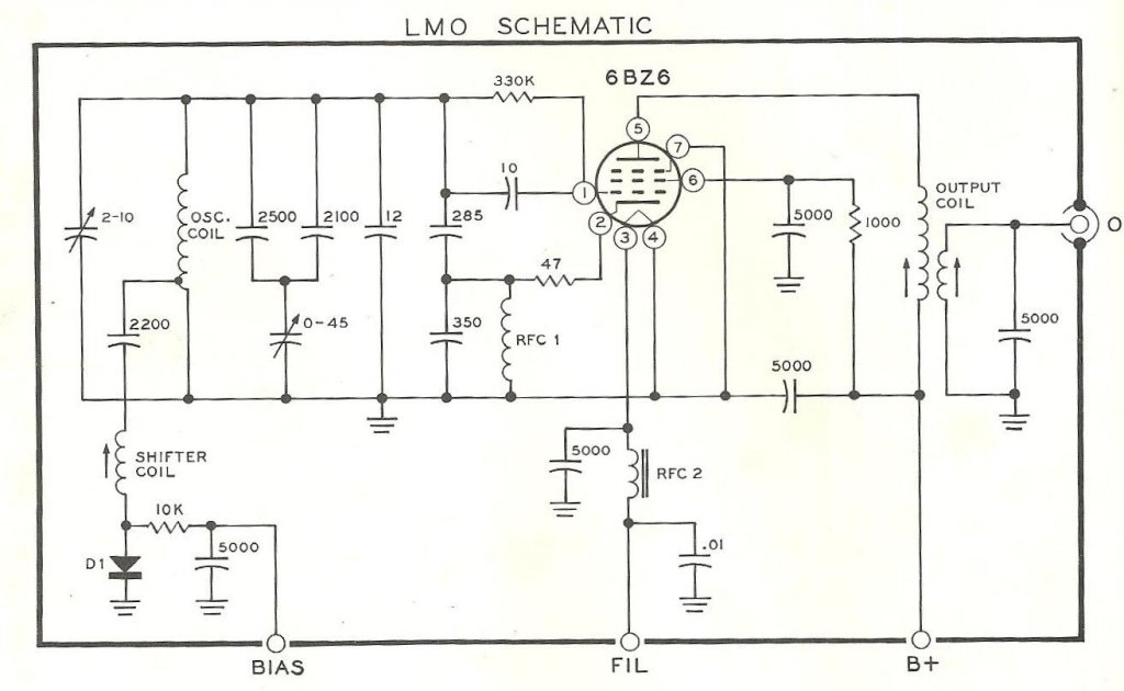
Got to work a bit on the receiver today. It seems I'm finding more issues than previously detected. I know I'm not a professional at electronics but it does erk me that I have missed what seems to be a simple matter. After removing the faceplate I was faced with a decision to remove the LMO or not to. I chose to remove it after noticing wrench marks around the screws on the tube-side of the box. After remov the LMO from the chassis I pulled the side plate off and took a gander at the parts noting the carbon composition resistors in there. Even though the schematic is one of the LMO's used, it does represent mine. There are a few more resistors in there that are not on the schematic. What was done and when isn't clear but the grease that was in there is crusty as expected after fifty years. There's nylon pin at the end of the worm drive shaft and the VC shaft.Now it is said that you cannot take off the other side plate because the VC is attached to it. Mr Sumption states it would mess up the calibration/alignment and claims it's a devil of a time to get it right. That may be true so I took the end plate off instead that faces the back of the dial and tuning knob leaving the variable capacitor and it's associated connections alone. This gave me direct access to the gear drive so I could clean and lubricate it. While turning it I noticed the shaft was turning inside the bushing on the stack of stop-washers to limit the travel of the capacitor. I pulled the stack apart, cleaned it and the shaft noting where marks were made from the setscrew. There were two sets confirming it had been taken apart. There were also a couple of score lines from the setscrews slipping. The receiver might have gone to Heathkit for servicing after the kit had been built or was an assembly line reject unit sent to the service department for repair. The two sets of setscrew marks on the control shaft looked the same telling me it had been that way for a long time. Since it never was on frequency when I did use it those few times, it makes sense now as to why. I thought it was because the friction wheel attached to the tuning knob that rotates the dial that, in-turn turns the worm driveshaft, was slipping. This is fairly common when the discs on the tuning knob shaft wear out.
The document I referred to in the last post by K9STH-Glen E. Zook, was read through a few times to make sure I was familiar with the part of the process I was going to have to do. However, it has no instructions to perform a repair on the calibration or alignment for it. It appears everyone is supposed to toss out the old one because you can't rebuild it. Hogwash! If it was built, it can be rebuilt. I do not have any info on alignment procedures but will try to contact Mr. Sumption for advice or the Heathkit group on Yahoo Groups.
As for cleaning, I used CRC's electronic cleaner being careful not to get any on the inductors. This did a good job of getting the old stuff out of the ball bearing on the main shaft of the VC and the input shaft of the worm drive. Mr. Sumption used synthetic 10W-30 motor oil. Probably because it has detergents in it and doesn't gum up with paraffins like conventional oil would. I prefer Labelle 108 synthetic light oil and their 106 PTFE grease I used when I was working with H.O. scale model trains. Grease for the bearings and stop-washers while the bushings get the oil.
As noted by Mr. Sumption about the ground wiper on the main shaft of the VC, I cleaned that area free of the crusty grease as well and put in a drop of the 108 oil. Some will say "For God's sake don't use oil! Oil makes a good insulator!" To that I answer, "But it had grease from the factory and it worked fine." Their argument doesn't take into account the wiper's spring force and can cut through the oil film even while the shaft is turning. It's doubtful you can turn the shaft fast enough for the wiper to hydroplane on the film of oil.
Now I've reached a point where I'm looking deeper into the mechanism and something caught my eye that may have just nullified the work I've put into it thus far. Have a look at the photo.

Do you see it yet? If not, scroll down for a close up.

**Update - Not that this is new info to anyone out there that has dealt with Heathkit SB series rigs for years but I compared the LMO's in my SB-401 transmitter and the one my Dad gave me. Both have the same part number stamped on the LMO. There were two part numbers that I'm aware of. The ones I have: 110-40; and one I saw in a photo of an earlier SB-301: 110-32; which I've heard is not as good.
If the SB-301 LMO does fail, I can use my 401 as a parts donor and keep the one my Dad gave me intact. I'd rather have his 303 and my 301 receiver working with only one operational transmitter if I have to.
Below are several photos of my LMO as a visual reference. As usual, click on the photos for a larger version.
 |
| Odd there's a hole between the can of the inductor and the adjustment screw. Directly behind that screw is the screw that holds the VC's ceramic insulator on that end. The crack passes through the hole in the insulator to the edge. Only thing holding the piece in place is the tab soldered between the back of the insulator and the VC frame. Makes me wonder if the screw was tightened too much causing the crack. Bother's me the LMO could have been in the reject pile and was repaired before being put in a kit. |


 |
So I have some more work to do. Now that the LMO is off the chassis I can turn the chassis upside down and begin reinstalling components and reconnecting wires. Might as well. It may take a while to find a good LMO for this rig.
73!
_____________________________
June 30th, 2019
Just not feeling it tonight so I'll just mention that I ordered the insulated shaft coupler for the Preselector. This coupler insulates the adjustment shaft from the variable capacitor's main shaft to prevent shorting, ground looping, etc. It is necessary and I wasn't sure about what to use. I was originally looking for brass couplers and came across this store on ebay. The original coupler has two cracks in it and got smaller when I loosened the screws. Retightening them confirmed they go all the way through and felt it had a good lifespan for the material it was made of.Though not part of the project I did also order a Hustler C23 ball mount and Procomm JBC305SS heavy duty stainless steel spring for the XJ-7100 project. The new spring will replace the rusty one on there now for the Icom IC-7100 that will be reinstalled into the vehicle. The rusty spring was made of standard spring steel with a poorly done chrome electroplating. Some polishing with the Dremel may stave off more of the rust for a little while as it sits on the other ball mount.
The new ball mount ordered is identical to the one installed on the passenger's side now and will mount the 102 inch whip antenna on the driver's side with the rusty spring for now until I get another SS spring. The Hustler and ProComm SS springs are made by the same company and both are roughly the same price. Hustler is found mostly in some better retailers while the ProComm brand is mostly found in truck stops for the same price.
This constitutes the last of my orders for anything for a while. If you want to know why, please read my post in Shack Happenings from today's date.
73!
___________________________
July 28, 2019
I did manage to get my workbench reorganized a little to make more room for the projects. Right now I'm fighting a broken caster on the chair and a solution. Still, I have gotten a little bit done on the 301. With the IF and RF boards already back in the chassis I started following the assembly instructions using the Bottom Chassis Wiring section to start reconnecting wires. I am up to the middle of page 40. It's not much progress but it is progress.No photos tonight as Google has shut off Google Photos automatic syncing with Google Drive. I'm in the process of making sure all of the photos are on Drive before deleting and removing Photos from my phone. They are making it much more difficult to use their products just because stupid people can't understand how it worked and don't want to figure it out. Sorry but this change is worse than their abandoning of G+. I can only ask: "What's next?"
73.
____________________________
July 29, 2019
Tonight's work was a bit more productive as I continue to run through the assembly process on the Bottom Chassis Wiring.
I know it's not much of a picture but I lost the others I took previously trying to get to my drive. I deleted them before I confirmed they had actually copied so this is what I have from tonight's work. I have completed all steps through the end of page 43 which ended with the .005 1.4kV capacitors. I use X1Y2 type safety capacitors instead as these will fail-open instead of fail-short like the old capacitors would do. I could put one across the leads but decided against it since this rig has a fuse. I need to mark the power cable to note that side as being the HOT or Live side since the power cord is not polarized. The cord is still flexible and tests good without any cracking or dry-rot like stiffness.
So far the second lamp is proving its worth by eliminating hard shadows cast by the other. The work is brightly illuminated with Daylight type LED bulbs as mentioned before and I am unable to find any noticeable noise here in the shack unless I put the little AM radio right up next to the bulb.
73!
______________________
July 30, 2019
Greetings! I did a little work tonight as well even though I'm not feeling very good. Seemed to be tired a lot lately as I put in a lot of late nights on other stuff. Sleep deprivation I think.

Now if you recall this isn't a complete teardown and rebuild. This is to restore the rig to operating condition with some clean up so many items are already installed that were not requiring their removal in order to remove the IF and RF boards.
The top photo shows the two X1Y2 safety capacitors I installed last night. The second photo shows the start of component installation on page 46. Most of the wire connections are done for this section as I have completed or verified all steps up to the end of page 45.
The blue E-cap is a Nichicon 10µF 160V and the two gray ones 10µF 160V made by Illinois Capacitor. I wanted to use all IC brand parts but I ran out and decided to put the Nichicon by itself and mate the two IC branded E-caps.
The instructions leave a lot of (NS) connections which can make for those pesky troubleshooting issues related to unsoldered joints. I really want to tack these parts in but decided to do it according to the instructions. We'll see if I wind up with any missed solder joints or not.
That's it for tonight! Thanks for checking in!
73!
________________________
August 3, 2019
Good evening, or rather good morning as it's past midnight as I finally get around to posting. Below is a pic of where I'm at now in the project.
Finished the bottom chassis wiring but I still have unsoldered connections. I went back through the instructions and found a couple that were missed but there are a few more that haven't been called to be soldered. I know there are three from the LMO and I counted four. We'll have to see. As I was resoldering some connections I noticed a modification I hadn't noticed before. There is a 2.2 phenolic or molded capacitor attached between one spare jack on the back and a trace on the IF Board. The person who installed the modification looks to have wanted to tap an IF signal for something. When the unit is powered I'll take a look at what frequency it's operating at. That should give me a clue.
So the LMO is mounted and lined up parallel to the front of the chassis. The dial pointer drive is installed now. The control shaft on the LMO has been rotated fully counter-clockwise and the dial has been set in place.
I hope the LMO works and it reasonably close to its operating frequency range. We'll find out during the initial configuration and testing phase. I'm getting close!
73!
_________________________
August 4, 2019
Good evening. Tonight's posting shows a little more detail of the work completed today. During the day I also had a couple of other things I wanted to get done. One of these was to install a second 102 inch whip antenna. Just as I was getting ready to carve out the hole with my Dremel a loud clap of thunder made itself known. Not desiring to test if I'm a better conductor over an antenna, I left it installed as a test fit and tightened down the main nut holding it on the mount, grabbed the phone, closed the rear hatch and ran inside just as the rain began pouring. After the storm passed I went back out to make sure it was secured and ready for road travel before returning to the SB-301.So back to the SB-301.


It's finally looking like a receiver again. It's taken longer than I wanted partly because of my frustration with the messy workbench I cleaned up, I soon discovered I couldn't find things. I thought I had all the parts for the receiver put in one box but the red/black leads for the meter have yet to turn up. I will continue with the work until I have to have them. It's not long in coming so I may have to improvise and use some other wires from another Heathkit. I don't have any 20AWG solid core wire. I should get some as I may have to remake the IT-28 main harness. Wire is expensive but necessary.
So that's where I'm at currently. Hoping to get to the "Initial Testing" phase by the weekend.
73!
___________________________
August 5, 2019
Just wanted to offer up this pic from tonight's work.
I apologize for the tilted angle. I might have a rotated sensor as it looked straight on the phone's screen. At any rate, I have completed the Top Chassis Assembly. The knobs cleaned up pretty well. The main dial operates smoothly too. Next is DeoxIT'izing the rotary switch wafers, potentiometers and lubricating the bushings and ball steps that hold the control shaft in place. I did not do this before now as I would not be using really anything at this point that would take off the stamped text on the chassis. I wanted to work this portion as though it were a regular maintenance routine to get the feel for such an operation.
I've printed off the Initial Test, Alignment, Final Assembly, and Installation instructions. Hope it passes the tests.
73!
______________________
August 6, 2019
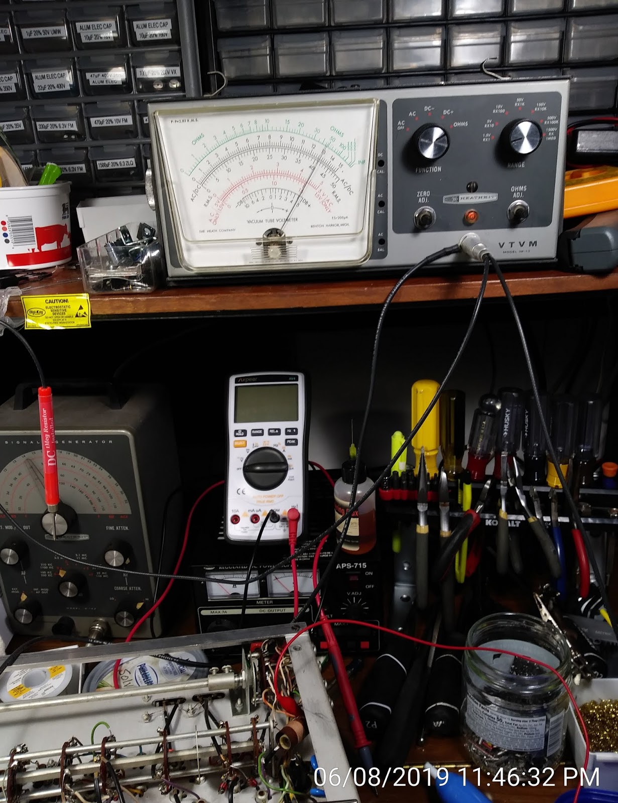
Wahoo! The rig passed the initial test! I had some contacts on two rotary switches that were giving me trouble. I think there was so much dirt on the wafer it was jammed under the contact finger. Another shot with DeoxIT D5 and several rotary actions later I tried the Initial Test again and it passed. I was a tad concerned at first since it was possible that a solder ball or a clipping had gotten trapped somewhere that was causing the erroneous reading on the IM-13 VTVM. So much fun using that! Can't wait for more measurements after the final three hookups for the filament lead from the transformer and reinserting the pilot lamps tomorrow evening. Once done I can test the tubes that came out of the rig and see which are good, weak, or bad. I have a TC-2 emission tester. I would like to find a Hikok dynamic tester but so far those are going for platinum so I'll wait. |
| The Initial Test resistance guide |
 |
| Waiting for the warm-up to finish. Time to make some tea. |
 |
| The last test of the procedure. Pass! |
have a good evening!
73!
____________________________
August 7, 2019
With the passing of the initial test I soldered the loose filament transformer lead for the test back on to the terminal strip. Putting the unit aside I pulled out the TC-2 Tube Checker and proceeded to test the tubes. Granted it's only an emission test with open or short tests but it's what I have.One tube didn't have any recognizable markings but looked exactly like a 6AU6. It could have been a 6BA6 too as it is set up on the TC-2 the same way. Those that have markings will eliminate the question of where it goes. The Compactron, a 6AS11, can't be tested with the checker as there is no socket for it. There wasn't any such tube that I know of in 1954 when this checker was produced.
The other tubes could be tested and tested good. The tube with no markings showed intermittent signs of failure anyway and was put aside. Old tubes that sit may exhibit this behavior until the impurities in the tube from out gassing of the material inside is handled by the Getter when warmed up. Each tube was installed in the checker with filament voltage applied for 15 minutes prior to any testing. This makes for a long testing sequence but worth it effort.
 |
| Waiting for warm up. |
I'll install them sometime later. I'm going to see if I can find a good used variac. I would rather not bring the receiver up on full power right off.
73!
_________________________
August 8, 2019
Got the tubes and crystals cleaned up and reinstalled into the receiver. One of the things I had forgotten to do was notate the tubes as they were pulled from their sockets. I have two that do not match what the book says. It never occurred to me substitutes would be made by an owner since I don't like modifying a rig from factory. However, I did suspect something of that sort when I saw the 2.2pF phenolic capacitor connected to a spare jack on the back. I found some documentation regarding mods but most were tubes, thankfully. Turns out the LMO and RF amplifier uses a 6BZ6 tube each. What I found were 6CB6A's and found one of the upgrades in later models included this tube. The last update for the LMO used the 6BZ6. I don't know if these 6CB6A's are original or the result of availability issues. I suspect they are original and the documentation I found online reflects the latest version.


73!
______________________
September 8, 2019
I'm beat so I don't think I'll get anything done on the SB-301 beyond the power up test I did last night. So far it is only using 1/2 of one amp in Operate mode and .4 of an amp in Standby mode. The tests were done on a variac and isolation transformer. The variac was brought up to 124VAC which is what is tested at the outlet in the wall. The unit specs say 120VAC even though this was in kit form in 1969. Knowing this I feel I can go ahead and run the rig at full power on the isolation transformer. This will help protect me while I do the alignment since the unit is not grounded, as designed back then.
I also discovered a #44 pilot lamp in the socket to illuminate the frequency dial. A major no no! Yes it's rated 6.3V but it uses .25A instead of the .15A of the #47. Shame on the builder/previous owner(s) for the case of, "It looks the same!" ignorance and shame on me for not checking it. So with one burned out and the other just wrong I ordered twenty more pilot lamps to have on hand. I thought I ordered some before but I guess I didn't. I have places to put the parts now so if I did buy them before, I'll have a place to put them this time. I ordered clear envelopes instead of colored ones. I like the warm glow versus the colored and like them far better than L.E.D.'s. Light from an LED is just too harsh. LED's have their place but not in my vacuum tube radios even though they make them with a color temperature similar to incandescent.
So I wait for the pilot lamps to arrive before doing anything more to the rig.
73!
_______________________
September 24, 2019
Greetings! I did some checking on the IG-102 RF signal generator to find it no longer is accurate to the dial even after all the work I've done to make it work. After spending time with the frequency counter, it does wander a little bit but for an analog radio it will be good enough at 10MHz and 15MHz. Since the receiver was designed before the 30 Meter band allowance, I used 15MHz for the initial testing to find where the LMO is synchronized on the dial. The photo shows it's off a bit. Instead of trying to align the rig with it this far off the mark I'll readjust the dial on the shaft since I know the LMO's variable capacitor is "center meshed". This helped me ensure the plates were not fully meshed nor fully un-meshed at both extremes of the tuning shaft stops. This leaves only the dial to be centered on a known frequency. Once that is complete I can begin the alignment procedure.I will be visiting family so I'm not sure if I'll get started on it until after I get back but I wanted to report the progress thus far.
The VTVM has been powered up and is working well so I'm confident I can get the voltages aligned as instructed in the manual.
Until next time!
73!
_________________________
October 12, 2019
Greetings All! Have been focusing on the Jeep lately and discovered the intake/exhaust manifold combo gasket is leaking at cylinder 2. I also went on vacation to visit my Mom and Aunt as well. It's been a busy couple of weeks.Let's see, the SB-303 was in need of an alignment and I went through the instructions over and over making sure I understood the procedure. There are a couple of things that seem ambiguous with the HET OSC alignment so I hope I got that right otherwise the rest of the rig is out of whack. Since I don't have a way to Zero-beat on 15MHz with WWV with the second receiver the book describes, I used the IG-102 with the internal 400Hz modulator to work it the best I could. I think my VX-3 can receive 15MHz AM so I will likely do this alignment over again. As it is, I still don't know how far off the LMO is and need to come up with a way to set it up in a test jig to see it's operating frequency range. I measured the capacitance and it's running 50pf range between 4.315-4.365nf on the main variable capacitor. I was worried about the trimmer on the LMO and was later confirmed it would not be able to adjust well enough for the final adjustment. It's close. It's real close so I am probably going to pull the LMO from my SB-401 and see if I get the same results. Remember that I cleaned the control shaft limit stops but wound up turning the shaft by mistake. This took it out of the factory adjustment. My 'fix' was to make sure the plated were neither fully engaged nor fully disengaged thus the 4.315-4.365nf readings. Had it been fully clocked in it would start at 4.300nf.
So I went ahead and adjusted the rotation on the shaft to help the dial read closer to it's range. Again, the SB-401's LMO is the same part number but won't be opened to keep it as my control measure.
The procedure of aligning the rig uses an 11megohm VTVM. A DMM with an 11megohm probe impedance will suffice but unless it updates the screen more than once per second, you won't see any "peak" movement which is what the VTVM or analog meter will show you.
First is the heterodyne oscillator voltages. Now I expected my readings would be out of whack just from the fact I replaced every resistor and capacitor (except the Mylars) with new modern manufacture ceramic disc caps and carbon composition resistors by a couple of my favorite mfr's.
In this procedure you will use the built-in crystal calibrator. The trick here is to set the dial so you hear the 1kHz tone. I used a sound analyzer on my phone called Spectroid. It's quite sensitive and the 1kHz tone was very prominent. After making sure the Preselector was in the correct position and the unit in LSB mode, I ran through each band to set the oscillator voltages before moving on to the Antenna and RF Amplifier sections.
These latter two sections are peaked with the S-Meter. All adjustments were done with a nylon or plastic TV Tuner or inductor slug adjustment tool. Mine are fairly short and red in color so I don't lose them. The ones my Dad had were the traditional milky white color and were a little longer I think. He still has them in his tool kit along with all the other tools of his past trade.
The alignment was completed and I tried out the radio. It sounds much better than it did before the procedure. I noticed the dial is quite a bit touchy. It's a pretty coarse adjustment to get it spot on to a frequency without distortion but that's the charm in my attraction and the challenge in operating a vacuum tube radio. A vernier adjustment would help greatly.
So with the functioning receiver, this project comes to completion.
73!
_________________________
_________________________
September 2, 2022
Thought it was over, ay? LoL. I did too. However the darn thing went silent right as a QSO ended. I was in the middle of another project and finally got to a stopping point to find another QSO or net in progress. To my surprise I wasn't hearing anything from the speaker! I thought maybe the audio section took a nose dive and decided I'd get it on the bench after the SB-401 project I had. Well, things happened and things have finally started getting back to flowing again.
The SB-301, as you recall, is the last of Heathkit's dedicated amateur radio vacuum tube receivers in the series. After this the SB-100, SB-101, and SB-102 transceivers became the flagship models until solid state models dominated the market.
Putting this on the workbench is kind of a pained experience. I know who did the repair work on it and having it fail makes me wonder what I did wrong.
After removing it from the case to gain access to the underside of the chassis, I pulled and tested the tubes in the audio circuit first. No problems there. I went on to the IF board and still no bad tubes. I did the resistance checks per the manual and there were a few borderline readings but still within tolerances. I burnished the contacts on the headphones jack then plugged it into the isolation transformer to ready it for live testing.
I fired up the IG-102 and the receiver to let them cook for a half hour to get them stable as possible. I had to shut the vent for the room so the A/C wouldn't blow cool air around and disturb the temperature around the chassis. I connected the vertical wire antenna and rolled the dial down to Zero on the 15MHz band. Since that is the only frequency I can get WWV, I selected AM first. Hearing nothing I chose USB and LSB and heard nothing. It was as dead as before.
Adjusting the preselector didn't do anything nor the converter to VHF1 to VHF2 and back to HF. Then I rolled the RF gain lever fully counterclockwise then fully clockwise and suddenly the speaker crackled to life. AHA! It's in the RF section!
I slowly moved the RF gain back and forth and found there was a definite dead spot but it was random in the lever's placement. I shut down the receiver, unplugged it and put some DeoxIT 5 Fader into the potentiometer. Several cycles of the lever later, I inspected the band switch wafers and saw I had missed the very first wafer on the front. A drop of DeoxIT 5 liquid and many switch cycles later I let the rig sit while I ate lunch. After coming back I plugged it in, turned it on and let it warm up again. Rolling the dial around 15.00MHz I was able to just pick out the minute tone after adjusting the preselector for maximum signal. The volume was wide open and it was barely coming through. Since I'd done the alignment on the Hallicrafters only a day or so earlier I thought I'd go ahead and just do an alignment procedure.
I got so far as adjusting the voltage levels of the band coils with the internal 1kHz calibrator. Tedious but was necessary as every one of them was out of spec by quite a bit. And that's as far as I've gotten. I'm working this weekend so no time. Maybe during an evening next week. Maybe Sunday.
That's it for now. Hope to have better progress to report soon.
73
__________________________
September 17, 2022
Time does fly when you're busy. I got back to this rig for a couple of hours and it was working initially so I dialed up 15.000MHz to listen for WWV. Once I got it centered up and playing I was able to test some voltages from the voltage chart in the OPR function mode. As I probed I noticed the sound of softly frying bacon sound starting up from the speaker. I've heard that before and knew something was about to quit. In my haste to get as many test points cleared I accidentally dropped my plastic slug adjuster tool into the radio. As soon as the tip hit the chassis between the 6AS11 Compactron and the IF board it went silent. I went to trying to find any voltages that aren't correct but up to a point, wasn't able to find any. The frying bacon sound comes mostly from a cracked resistor. As it heats up the crack gets bigger until there isn't enough contact within to keep the circuit complete. It was late and I shut everything down and watched some YT videos about my other hobby. Jeeps. I'm doing a regear in the next week and need to refresh my memory on the sequence of events since the rear axle was done. But I digress. I pulled each tube, cleaned the pins and the sockets, checked them with both the TC-2 and Conar tube checkers and all passed with high marks. I applied DeoxIT to the sockets and repeatedly wobbled the tubes in and out. No change.
Another week goes by and it's tonight when I get back to it. So I fired up the IM-13 and the B&K 1570A with a 10x probe so as not to overload the input on the scope to find where the signal dies.
I started working backward from the speaker to see where it appears to stop and in doing so discovered not recognizable signal at the input to the second IF amplifier tube. I try to check further back up the circuit but either my scope isn't capable of the sweep speed necessary to view the waveform(s) or there's something wrong further back.
I probe the HET port on the rear panel as well as the LMO port. The LMO port is rock solid. The HET...well, without a known waveform to be expected I guess I'm seeing what should be there. A combination of multiple signals as this is the mixed signal. The BFO port is active but very jumpy. I'm figuring that's one clue. It is possible the oscillator circuit is unstable and isn't able to oscillate reliably. From the scope's display it almost looks like it is running but interrupted with several spikes. When I pulled the transformer for this circuit all appeared to be okay. I had continuity in the coil but the dipped mica capacitor leads were so tightly wound I was afraid of breaking the super fine wire of the coil. I did reheat the solder connections with a single drop of RA flux each lead and reflowed the solder. The continuity or ohms did not change from before.
I removed the 6AS11 and checked it on the Conar tube checker. It's an emission checker and capable of checking the Compactron series of tubes. It even has a socket for the rare and short-lived Nuvistor. Everything checked with good high levels in the green.
I had to end the work session and right this up before it gets too late. I have plenty to do in the morning so a late night isn't in the plan. I am convinced the problem is a failed resistor. For now, I will probe the IF board for voltages instead of the the RF board. Reason being is I could hear the calibrator audio from somewhere in the chassis like maybe a tube plate singing. But if that's the case, why doesn't the audio hit the known good speaker? Very odd.
________________________
October 2, 2022
Just a quick update on the 301: It now won't put out any audio even when cold like it did before. I've downloaded the assembly manual and found the troubleshooting section to get started on. But alas Jeep trouble has kept me away from this. I may not have much time to work on this since October marks the point in time I may begin my business-hobby of repairing tube radios for a local furniture restoration shop. A pallet of radios is expected in the next week or so for me to choose one. Once I get the call, I'll start down that path. Until then, updates will be few.
TTFN and 73
_________________________
Comments
Post a Comment