Hello and welcome to my first project to restore my Heathkit SB series amateur radio set. This set and much of the test equipment was built by my Dad when I was about 4 years old. Join me on my quest to restore this vintage equipment back to operation. These posts are in chronological order from oldest to newest.
If you are new to this blog post, please grab a cup of coffee and make yourself at home. If you are a returning reader, grab that cup of coffee over there and jump to the bottom of the page for the latest date heading.
These posts and updates are in Commentary-style. There aren't any step-by-step instructions to restoring this piece of equipment.
List of web sites parts were procured:
Digikey - discreet components
Mouser - discreet components
West Florida Components (ebay) - 5AG-A Neon glow lamp
Kimco Distributing (ebay) - Kester 44 Solder
Great Estate Electronics (ebay) - potentiometer nut, washer, lock-washer set
Local sources:
Nick's Trains - Labelle 106 and 108 synthetic lubricants
Carquest/Advance Auto Parts - Quick Dry Electronics Cleaner
Here's a partial list of sites or publications I use as my project resources:
http://www.radiomuseum.org/r/heath_station_console_sb_630_sb.html
http://www.heathkit-museum.com/hvmtest.shtml
http://www.uv201.com/Clock_Pages/pennwood.htm
http://www.transcendentsound.com/Tubes_and_Circuits_by_Bruce_Rozenblit.html
http://www.surplussales.com/
http://www.tedss.com/
http://www.k4eaa.com/parts.htm
http://www.ohio.edu/people/postr/bapix/capchkr2.htm
http://boatanchorpix.x10host.com/
http://mysite.du.edu/~etuttle/electron/elect27.htm
http://tubedata.milbert.com/?db=1
http://www.tubecollector.org/
http://antiqueradios.com/
https://www.nostalgickitscentral.com/heath/products/test.html
http://www.tubebooks.org/Books/Zucconi_probes.pdf
https://maritime.org/doc/neets/mod06.pdf
http://www.hobby-hour.com/electronics/resistorcalculator.php
Note: I found that Digikey's 5-band resistor calculator couldn't figure the value of a 22 Megohm 1% resistor banded with Red-Red-Black-Green-Brown. In the fourth band, there was no Green available so I hobby-hour.com got the task.
https://frank.pocnet.net/other/Mullard/MULLARD_Electronic_Counting_Circuits_Techniques_Devices_20160521-0002.pdf
https://frank.pocnet.net/other/Sylvania/Sylvania_Technical-Manual_1970.pdf
http://www.tiffe.de/roehren/neon.pdf
https://ia601205.us.archive.org/24/items/GE_Neon_Lamps_1965/GE%20Neon%20Lamps%201965.pdf
http://poynton.com/notes/units/index.html
This site helps with proper notation of symbols and SI units.
Heathkit SB-630
1968 Catalog Prices
Kit SB-630.....................$74.95

Since there are three independent circuits in the SB-630, I thought I would offer a BOM list for the timer and the SWR bridge as two lists. I'm not going to be using Phone Patch so I'm not going to be rebuilding that portion of the circuit.
I use both Mouser and Digikey to obtain parts. I'm not doing a price comparison only if I can get everything or the majority of everything from one or the other. For the more rare or esoteric parts, I use Surplus Sales of Nebraska, ebay, For those wanting a ready-made cart of the electronic components I'm using, please have a look at my Digikey cart. It has all the resistors and capacitors you'll need to rebuild the timer circuit. I have not included the parts for the SWR bridge. That is on a separate list below.
My Digikey Cart
http://www.digikey.com/short/3dzfw5
SWR Bridge
2 - Hughes Industries Germanium Diode - 1N191 from Electronic Expediters Inc.
1 - 56Ω 5% 1/2W Carbon Composition Resistor
1 - 100Ω 5% 1/2W Carbon Composition Resistor
I am fully aware that I'm no expert in the subject of restoration of vintage radio equipment so what I say and do here may conflict with your idea of what's "right". If you have a constructive comment, please, let's hear it. I am full-time employed with the odd side job now and then so updates may have time gaps between them. All I ask is please be patient.
Heathkit SB-630 Station Console
What is it?
This unit is actually part of a three-unit monitoring system for the SB series transmitter/receiver sets and transceiver units. Smaller single-purpose accessories may duplicate the functions combined in these pieces of equipment. The three units of the station monitoring system in reverse numerical order are as follows:

The SB-630 Station Console in the picture at left featured a forward and reflected power indicated with one meter and selected with a rotary switch; 24 hour Numechron "digital" clock movement; visual or visual/audible FCC 10 minute call ID reminder and a phone patch circuit.

The SB-620 Scanalyzer was an early type of pan-adapter driven by an IF signal port on the back of the receiver. This offered the operator a view of signals present around the operator's tuned frequency with a selectable 10kHz, 50kHz or up to 500kHz in variable bandwidth mode.

The SB-610 Monitor Scope was designed to monitor incoming and outgoing modulation. This helped operators from splattering outside his frequency requirements and improve his modulation quality while transmitting. It is capable of showing trapazoid geometry when used with an amplifier. It also offered the operator a way to monitor incoming signals for modulation quality as in RTTY operations as well.
I only own the SB-630 and it will be the first of six pieces to be restored. The unit is in good shape for it's age. My father built it as well as an SB-401/303 combination transceiver set with the SB-600 speaker. I have these as well as some of his test equipment that also need restoration. All of the pieces don't appear to need much cosmetically as none have been in any smoking environment where the tar and nicotine and carbon from the smoke settle, discolor and otherwise poison electronics. However, the paint is showing it's age with the typical flaking off the aluminum covers from high humidity.
A typical bad-cap replacement will be performed using new parts. Before that, the unit will be partially disassembled and cleaned up. Once the new parts have been installed it will be calibrated, aligned, and reassembled for testing. I fully expect to replace several parts as they are now in my age range. Fifty-plus. Hopefully I won't need as much in the next several years. ;-)
A little back history about my involvement...
I remember I was two when my Dad built a Heathkit GR-180 color television. I couldn't wait to play with the big box it came in and did so for quite a while until it just wasn't a box any longer. When he finished with it and calibrated everything, we sat back and watched our first color TV. As the years went by I would turn the TV on and still go watch for the orange glow of the heaters in the tubes and knew there was something special going on. From those early years, I was fascinated with electronics, computers (Hollerith card era) and other mechanical things that had gears, chains, linkages, pulleys, belts, knobs, and wires not to mention lights. I watched him build the SB-401/303 (solid state receiver) series transmitter/receiver pair as well as the station console and the speaker.
Though he is not active in amateur radio any longer, of the items I have from him are the aforementioned radio units, an Icom IC-745 (non-working), a Paco S-55 oscilloscope, Heathkit TC-2 Tube Checker (as opposed to true 'testing' of the tubes like a Hikoc can) and quite by accident, his old Heathkit IG-102 RF Signal Generator I picked up at the local RARS hamfest this year (2017). I needed an RF signal generator and wanted the one he had used to calibrate many things over the years with including the radio set.
I had bought my own SB-401/301/600 set with the intention of restoring it until my Dad offered his to me. Now I'm interested in restoring both sets. Other pieces of equipment I am looking to get hold of is a VTVM (bought an IM-13 May 12, 2017) and a capacitor checker by Heathkit, of course. For now, I can get away with a DMM but when it comes time to calibrate everything, a VTVM will be the meter of choice.
Which brings us forward to 2013 where I finally decided to get my General Class license. As my reward for passing the "grade", I bought my first working HF rig at the hamfest in Huntsville, AL. A Kenwood TS-450S/AT now sits on my desk to the right of my keyboard as I write this.
Now in 2017 I feel I have paid enough to the School of Hard Knocks to really want to get back to my real interests in electronics and enjoy a hobby again. Call me a Radio Angler or a Signal Wrangler, if you prefer. Any time I get a chance to listen I fish for radio signals while sometimes wrangling station signals to pull them out of the noise floor.
After several weeks of on and off researching antique radio forums, component substitutions, test equipment, history, and performance specs, I think I've got enough info to begin the restoration process. Though this is the simplest piece of equipment I have, I feel it is a good re-introduction to the technology and design of the time. So without further adieu, let's begin...
I started out taking a lot of pictures after getting the chassis out of the cover to document as much of the condition and of the actual connections themselves as I could. It would also serve as a visual reference should an assembly manual not be available in the next few weeks. A few are shown below.

Inspection
Removing the screws and pulling the chassis out now done, the naked unit sits on the desk waiting, in all it's grimy, dusty glory.
 Despite the pictures here, the chassis wasn't that bad. The underside of the
chassis was very clean indeed. The top of the chassis was the typical
dust accumulations of a combination of nearly fifty years of service and
storage in various locations. Mostly basements.
Despite the pictures here, the chassis wasn't that bad. The underside of the
chassis was very clean indeed. The top of the chassis was the typical
dust accumulations of a combination of nearly fifty years of service and
storage in various locations. Mostly basements.
 None of the equipment has been
submerged but has been exposed to periods of very high humidity during one of the basements
having flooded, twice. The high humidity resulting from the flooding doesn't
show up except for the flaking paint on the SB-303. So far, there is no corrosion of the aluminum parts
and as far as I can tell, the wiring or switches. No fluffy green or
white stuff is visible.
None of the equipment has been
submerged but has been exposed to periods of very high humidity during one of the basements
having flooded, twice. The high humidity resulting from the flooding doesn't
show up except for the flaking paint on the SB-303. So far, there is no corrosion of the aluminum parts
and as far as I can tell, the wiring or switches. No fluffy green or
white stuff is visible.
Cleaning
When considering cleaning of the chassis, I would cringe every time I read that somebody has used or recommended water, steam cleaning or the dreaded dishwasher. I know some have used these methods and claim they don't have any issues. I wonder if further inspection of those units now would yield corrosion and oxidation beyond what they originally started with before the cleansing. Since water is the universal solvent, water ingress of variable mica capacitors can leave residues from the water impurities. Water corrodes wiring by capillary action from the point the insulation ends up the wire under the insulation. There is no 'seal' even with heat shrink tubing. And forget about any textile covered wiring. No. Water isn't a good idea unless all wiring and parts have been removed where impurities will remain. A tunable radio is more desirable than one that now requires more work because using the water changed things.
 Another
method of cleaning I've read that is used is WD-40. Now it'll get a
lot of stuff clean but not without its drawbacks. While it cleans, it
will also leave a lubricating residue. This is good for rotary switch
shaft bushings. It will displace water from contacts like the pin
sockets of the vacuum tubes (valves). And it will leave a light coating
of that material all over the chassis to retard oxidation. The bad
part? You've spent all this time to clean the unit. Why would you want
to have a surface that attracts dust and dirt more easily now? If
you're selling it after restoration, think about how much the next
person will have to do to clean it up when it's time to work on it. Pay
it forward with quality. A shortcut is likely the longest route.
Another
method of cleaning I've read that is used is WD-40. Now it'll get a
lot of stuff clean but not without its drawbacks. While it cleans, it
will also leave a lubricating residue. This is good for rotary switch
shaft bushings. It will displace water from contacts like the pin
sockets of the vacuum tubes (valves). And it will leave a light coating
of that material all over the chassis to retard oxidation. The bad
part? You've spent all this time to clean the unit. Why would you want
to have a surface that attracts dust and dirt more easily now? If
you're selling it after restoration, think about how much the next
person will have to do to clean it up when it's time to work on it. Pay
it forward with quality. A shortcut is likely the longest route.

Now
all this doom and gloom over water may have anyone wondering what else
is there to clean with? Well, water. But not straight water and using
it to just blast it clean with the wiring and other stuff still
mounted. There's a better way to use the water for a higher quality
return on the work you put in. I've read about the use of 409, Simple
Green, window cleaner, ammonia and such too. Some do not seem to do as
well and some do better. You'll have to figure the trade-off. This
next cleaner I'm about to use is Super Clean, made by Castrol. It is
biodegradable and phosphate free. Now I'll admit it's not as
eco-friendly as the green stuff and according to the Safety Data Sheet
it is caustic to metals like Purple Power or other strong cleaners.
However, it has complete water solubility so it can be thinned with
water to soften its chemical effects. It will dissolve grease, suspend
oil and dirt so it can leave a clean surface behind after a wipe-down
with a damp cloth. Either water or some other liquid getting on the
wiring is bad so they must be protected from where the insulation ends
and exposed wire begins. Plastic is another material that doesn't do
well either. Phenolics can be damaged and the list goes on. So where
do that leave us? Basic, honest to goodness careful cleaning if
components are still mounted. That means Q-tips, damp lint free cloths
and patience. In the end, you'll be glad you spent the extra effort
even if you don't sell the radio.
I saw one restored radio where some kind of liquid electrical tape was used on each connecting point to try and seal up the exposed wire where the insulation ended. Looked kind of weird and maybe more trouble than it's worth when a repair is required but if that's what it took to protect the wiring in the humidity of deep south Georgia in August, then more power to them.
SWR Bridge
Figuring there are carbon composite resistors inside the bridge, I decided to rebuild it with new components. First, I had to remove the cover which would allow access to the two wires running through the side of the box to the meter circuit. Two disc capacitors, two 1/2 watt resistors and two germanium diodes are all the electronics making up the device. Germanium diodes were very common in those days and had excellent sensitivity. Today, a Schottky signal diode (named after German physicist Walter H. Schottky - Schottky_diode) would most likely be used instead.


After disconnecting the wires, I could take it off the chassis and disconnect the components for testing without having to work with the main chassis.
 As you can see, the resistor on the output side of the bridge read 57.9Ω. The value should be 56Ω. For a carbon composite resistor, it is within its Gold Band (5%) tolerance by .9Ω.
Since I'm not trying for a gold medal in a concourse restoration of
vintage equipment, I'm not concerned with what was used in this device.
I'm more concerned with quality and accuracy of said device. We all
know Heath's kits are only as good as the parts and their builders, but
where improvements can be made economically and have it perform better,
I'm for it.
As you can see, the resistor on the output side of the bridge read 57.9Ω. The value should be 56Ω. For a carbon composite resistor, it is within its Gold Band (5%) tolerance by .9Ω.
Since I'm not trying for a gold medal in a concourse restoration of
vintage equipment, I'm not concerned with what was used in this device.
I'm more concerned with quality and accuracy of said device. We all
know Heath's kits are only as good as the parts and their builders, but
where improvements can be made economically and have it perform better,
I'm for it.

The next picture to the right shows the input port resistor at 109.8Ω. This is banded as a 100Ω, 5% tolerance resistor. This is well outside its tolerances so this will be replaced as well.
Now one of the pieces of test equipment I really wanted to get my hands on is a Heathkit IT-11 or IT-28 capacitor checker. The only difference I could see between them was the IT-28 could be configured for 240 volt mains like Europe and many other countries use. Other than that, I prefer the IT-11's two-tone grey over the brown. With this I can test not just capacitors but also their leakage point. Disc caps are cheap and I'd just replace them if they look bad. But electrolytic, mica, poly-types and paper types can show they work just fine at lower voltages. The IT-11 and IT-28 can charge a cap up to 600V so you can find their point of failure up to a 600V value. Mica and poly-types are very durable but can fail due to perforation of the dielectric material or mechanical damage. Electrolytic types fail mainly from drying out if wet types or the dielectric is physically damaged from heat stress like the paper types. There is the process of re-forming a capacitor but it can still suffer from perforation and you might not know it until it takes out an expensive transformer. If there are capacitors in there made as a silver mica, you also have the added problem of whiskers growing through the dielectric and shorting out internally through the adjacent dielectric layer.
Stay tuned for further updates!
Back again today having had some time to contemplate the SWR bridge and other items. After testing several of the old carbon composition resistors in the timer circuit and all, so far, are out of spec by any amount, I've come to the conclusion they all need to be replaced. If the rest test as bad, then what to replace them with? In the bridge you can't use any resistor that has inductance. This rules out any kind of resistor that is constructed with a wire-wound construction or layered on a ceramic rod, coated with resistor material and helical cut to fine tune the resistance value. That helical cut is indeed a coil. This rules out Carbon Film, Metal Film, Metal Oxide, and Wire-wound. So far, I have not found any manufacturer as yet that produces a resistor that can exactly replace a carbon composition resistor.
So now the question is, what type of resistor is used in modern radio RF circuits? That's right! Surface mount! Those tiny little chip type resistors that require a macroscope (for everyone else ) or a microscope (for those of us using reading glasses). One of those USB microscope cameras sounds like a good idea right about now. Wished I hadn't passed up that deal at the hamfest last month.
As for the carbon compositions.....I've read that the Allan Bradley's were top-notch MIL-spec and tedss.com has them. Knowing that the carbon comp's all rise in value over time with heat stresses and moisture absorption through the junction of the leads and case joint, it would stand to reason that even stored and unused, they can be compromised. So I should ask the question, how exact am I willing to attempt to get the SWR meter to read? If it's to be used, it should be accurate right? I'm learning that accuracy isn't always attainable due to the rules of diminishing returns.
I discovered an open rectifier (D5 on the schematic) so both will be replaced with Vishay 1N4007-E3/54 pieces.
New electrolytic caps (C26 and C27) have been procured early in the hopes that the resistors were okay. But it wasn't to be that easy. "Nothing's ever easy." -Zeddicus Zu'l Zorander

I also snagged a NOS Sylvania OA2 at the hamfest last month (April).

In the meantime I am putting together an extended parts list for this unit for a complete restoration of the SWR circuit. Since I will not be using Phone Patch, I won't be replacing any of those parts. A note to any future owner will be taped to the chassis to document the changes and omissions. The parts lists will be saved in my Digikey and Mouser accounts for future reference. If nothing else, it'll be restored to original operating condition even if period tech can't be improved upon with modern manufacture.
More testing revealed all remaining resistors are out of spec. So the decision was made to replace all fifteen resistors in the timer circuit plus the two in the SWR bridge. I decided to go with Metal Film from Vishay as they are not part of an RF circuit. Most are 1% with 100PPM/C The single 22k 2W resistor (R38) might be better suited as a Metal Oxide but I'm not sure. I bought both in case I change my mind.
I added two sets of capacitors and two sets of carbon composition resistors for the SWR bridge (is it really a bridge or a resistive mismatch detector?) so I could play with the values to see if there is a difference between the stock set up and changing them. Heathkit shows one 56 and one 100 Ohm resistor used but both capacitors are .005uF. I've built a few SWR "bridges" using two 100 Ohm resistors and two .001 caps. Not sure why Heathkit engineers designed it this way. I would love to be able to talk to one about this. The circuit appears inherently imbalanced thus making a measurement really inaccurate thus increasing the stigma about lousy SWR readings on Heathkit meters. Maybe I'm just missing something here. Or maybe the imbalance accentuates the reflected power since very specific measurements to where these components are attached on the rods.
So my order to Mouser has gone in and now I wait. I saved the cart as a project and will tweak it a little bit for the bridge in case anyone wants to get a list of the resistors to purchase for their own resto-mod.
Until next time! 73!
Smitty
http://www.w5kub.com/
SB-630
I received my order from Mouser and checked in the manifest. I also received the capacitor order from Digikey for the SB-301. I'm in the middle of cleaning out and relabeling an old steel cabinet with 60 plastic box type drawers for the resistors. I have two but a few of the little plastic compartments are missing and decades of dirt, dust, and other unidentifiable things have stuck to it. So the drawers were emptied of useless stuff, and useful stuff was transferred to the other one in preparation for a trip through the dishwasher. The drawers at least. I'll just wipe down the cabinet with Super Clean and a damp cloth. I think I got these cabinets back in the late 70's as either a birthday or Christmas gift. I do remember I got them before Skylab came out of orbit and burned up. I ordered a new cabinet (sadly it's plastic) that is a tad wider and not as tall but still has 60 drawers I'll use for the capacitors. That one should be ready for pick up in a few days.
As for the chassis, I haven't yet started cleaning it as I want to be prepared with all the parts I'm going to replace. Namely the carbon composition resistors and the two Mallory 100uF/200V electrolytic's. Though I am using a comment style of project reporting, I hope it will be easier to follow the major work going on with this project.
_________________________________________
73!
_________________________________________


 With the clock removed, the top of the chassis looks pretty bare and desolate. With the dust and dirt it might look like a wasteland at 100x magnification. Now I'm really sorry I didn't get one of those USB microscopes or endoscopes for close it views. Even with my glasses I can't get too close without a magnifier these days.
I wasn't planning on removing the face plate but the thought that I might not get a chance to do this again loomed over me. I decided to do it so I could clean it up and scan it to get a pristine image of the face plate for future use.
Removing the knobs proved difficult only because I couldn't find my SAE Allen wrench set. When I did, it didn't have the 5/64ths size. So I picked up a set by Husky (my preferred brand) from the Depot on my way to church. On the way home, I needed cotton swabs, flat washers and rubber washers. Well, I got the cotton swabs! Yay! But I forgot both the rubber and 1/2" flat washers. Booo! The rubber washers are used for the clock mounting to offer some noise and vibration isolation from the chassis. Without them, the motor noise would translate through the chassis making the motor and gears much louder than acceptable. The flats are for the mounting nuts for the panel controls as three switches are missing them. Not sure if the Depot will have them but I will check around. If I can't locate any, I'll put the ones I have on the rotary switches first. I don't anticipate using the Phone Patch but I'll service it anyway. Once the knobs were removed I remembered the power knob for the alert timer didn't seem to work right. Removing the knob revealed the problem. The shaft coupling sleeve had split and tightening the set screw will not have any real effect. Now I looked at all the shafts on the controls and noticed none had an index flat on them. Sooooo, I'll be carefully modifying the shafts of the rotary switches to give the set screw a better seat. The variables don't need much torque to use but the rotaries can stress the old plastic more if the screws have to be tighter to prevent slippage.
Removing the nuts attaching control wires for the SWR/PWR meter was difficult. I needed something the hold the base nut in place while loosening the nut that attached the wires to it. Once done I could tell there is something on the threads. Corrosion or thread-locker. I can't tell. I will find my Dremel and the wire wheel to clean them and the lugs. Removed the meter and cleaned it up too. It came out looking practically new using the damp cloth with soap and water then wiping it down with plain water on a cloth. To get into the crevices of the details of the meter face was easily done with a cotton swap. Just the brass terminal studs need to be cleaned now.

Removing the pilot lamp was interesting. It took a bit more finesse than expected to get to the lead on the power switch for the timer. Trying to get the right angle for the solder sucker was a bit of a trick without burning through insulation elsewhere. A small puff of smoke and the telltale acrid odor proved I needed more finesse. Fortunately it didn't burn completely through the insulation. Removing the pilot lamp was a milestone in the project. I could now remove the face plate.
The push-nuts holding the Heathkit badge and meter bezel weren't hard to get off. The clock bezel and chromed metal Heathkit badge were removed and set aside for cleaning. The badge really didn't need more than a cotton swab run through the channels of the casting. The bezel was cleaned with the soap and water mix on a damp cloth then wiped with a plain water damp cloth.

The face plate showed a little bit of dirt that came off easily and brightened the silk screening a tad. I probably could do more but don't want to risk removing any of that to make it perfectly new looking. Careful wiping with with a damped cloth with soap and water cleaned up the face plate well. A wipe down with plain water damp cloth finished the cleaning process. The crinkle finish remained as did the silk screening. After the cleaning I fired up the scanner and scanned it in several different modes. I'll go through them later for a more detailed evaluation but a quick look appears they are good quality images. With the right software, one can at least be used as a template to make a vinyl over lay in case the worst happens. If that happens, I'll either opt for a Collins-like color scheme with a darker face plate and lighter cabinet or go the Hammarlund route and go all black with white lettering. I wouldn't do that with these pieces my Dad owned. The SB-401/301/600 set I bought would be a modified color scheme though. They were owned by a smoker and the paint is almost completely flaked off the cabinets down to the bare aluminum. Just handling them has left a trail of green paint flakes. Not really looking forward to cleaning those pieces just yet.
Maybe I'll polish the cabinets and seal the aluminum (aluminium for our British friends) like mag wheels on a hot rod with a Candy Apple Red face plate with larger white lettering, black knobs with polished gold centers and gold anodized knob skirts just for the shock value. :-p The face plates are still okay but I'm not sure what will happen when I try to clean them, hence the need to scan the good ones from my Dad's set.
Now I've begun removing components from the chassis to get to other items I need to remove to clean the top deck of the chassis like the power transformer. One of the transformers mounting nuts was underneath the old Mallory electrolytic filter capacitors and so they had to be removed. Next, a pair of rectifiers were removed to get to the other nut. Just to see if they were still okay having thought I had found a bad one, I put them on my meter.


As you can see in the photos, one showed a forward resistance of 700Ω while the other shows 688Ω so no open rectifier. Hmmm. Testing in-circuit shouldn't have given me that open reading and I later discovered a problem with my Common probe so I replaced it with another. I tested them in reverse as well just to be sure and I got nothing so these are good but I consider them mismatched. I'll save them for another project. I'll replace these 57-27 SENS 600V 1A rectifiers with a couple of 1N4007 1000V 1A pieces I already have.

So this concludes today's work. It is now 0100, May 29, 2017. Remember our fallen brave men and women on this Memorial Day whom gave their lives to protect the freedom's they fought for that we hold dear no matter which war they fought in.
_________________________________________
I started cleaning the top of the chassis without removing all of the parts except the clock. I wasn't planning on doing a complete disassembly down to the individual parts and reassemble it as a new kit. Originally it was just a cap change. Next the resistors tested faulty and while I'm so deep into this I decided to get as much of the top deck cleared off to clean it. I wasn't going to desolder the transformer so I unbolted it and raised it with what little slack there was in the wires to get some cotton swabs underneath to clean under it. The area was pretty clean to start with and after cleaning around it, I mounted it back in place to prevent any undue stress on the wires. Breaking those off won't be catastrophic but would be a major pain to repair. Unwinding and rewinding transformers isn't at all fun.
Anyway, the cleaning process isn't hard. But I am finding out that Super Clean from Castrol may not be the best at cutting the dirt. That or the exposed part of the chassis has some other kind of deterioration that needs to be addressed. What's happening? After an initial rubbing off of the dirt with a dry rag, the dirt is coming off so thick with the Super Clean that it's leaving a residual layer behind. After repeated cleaning using clean spots on the rag, the residue remains. So is it a residue from the cleaner or a quick form of oxidation of the surface? I'm also noticing a distinct line of "pristine" surface delineated by the SWR bridge box and it looks a lot like the surface underneath the transformer. It's quite a bit more shiny than the long-term exposed surface. So the next step will be trying out some Duragloss 821 - All Wheel Cleaner if I can find locally. Otherwise I'll use the Eagle One brand of the same. I should follow it up with a protectant if I do go this route entirely.
Updated note: Wasn't able to find either wheel cleaner but the XYL told me she had some from Meguiar's in the car-care box. I also found Meguiar's Step 2 Cleaner Polish. Used some of that to work on the corroded spots. It also shined up the aluminum quite a bit. I did do some general area cleaning with the polish too see how shiny it would turn out. The chassis had a nice shiny sheen to it but a bit too bright for my tastes. To dull it back down to the original tone I used the wheel cleaner. Once done I then applied Duragloss 101 Polish Cleaner to seal up the surfaces and it came out nicely.
The large one in the upper right corner of the photo above is a real mystery as to why it's so large. There was nothing there but the dirt and thus hidden. However, all of the spots have centers indicating an event that began the corrosion process. An old solder splatter that ate through a coating on the chassis perhaps?

Some would say I should have put it in the dishwasher and be done with it. Like I said in my earlier posting, dishwasher safe, it isn't. It might clean it quickly but only if I completely disassembled it to a bare chassis preventing any water intrusion to where water should never be.
Before using the metal polish, I' shot the tube sockets with some electronic cleaner. DeOxit isn't available locally but CRC and Carquest QD Electronic Cleaner (made by CRC) are available at my local Carquest/Advance Auto Parts stores. I have some of the Archer cleaner left and will use that up first. I also have some of the Archer tuner cleaner with lube I'll use on the rotary switches once I find it somewhere in the closet.
If you decide to go to an old Carquest store or one that has been converted to an Advance Auto, ask them to check their Carquest warehouse if it isn't in the store. Since Advance Auto took over, many of the Carquest branded stuff is no longer in the store but returned to their distribution centers. If none are available, go to the shelf with the carb cleaners and look for CRC Quick Dry Electronic Cleaner. Home Depot also shows to have the CRC brand available.
Until next time! 73!
_______________________________________
 The capacitors came in and I was ready to start removing all those components and some that really had to be removed for the sake of getting to others. I did get a pair of Orange Drops to replace the two resin caps. One of them is overshadowed by the relay making it downright impossible to get to. I have considered moving the relay an inch toward the front panel and left edge of the chassis to offer more space. Not sure if I'll do that down the road. I did notice the Orange Drops aren't labeled as to which lead is the 'outer' shell contact point so I will fire up the oscilloscope and perform a test to see which lead is attached to it. If you want to see what I'm talking about, Mr. Carlson's Lab has a good explanation of capacitors and how to use an oscilloscope to check this very subject.
Backwards? https://www.youtube.com/watch?v=BnR_DLd1PDI
Which capacitor to use? https://www.youtube.com/watch?v=67M7fsbLUIU
If I ever do have the opportunity to purchase an IT-11 or IT-28, I will then have the ability to test any of my old capacitors completely. Since these checkers have up to 600V available to test leakage with I can rate the capacitors and allocate them to a better suited less critical circuit without tossing it out until it is completely useless.
Here's the current state of the project. Apart. With the exception of the shunt resistor on the reset switch, all other timer components have been removed. The two transformers on the right and the big TRW 2µF Polyester capacitor in the lower right is for the phone patch which I will not restore at this time. My primary goal is the get the timer working correctly and improve the meter accuracy.
You can also see the 3/16 amp slow-blow mains fuse in the lower center, the alert relay (loose) near top center and that scary buzzer bolted there to the right of middle center. Let me tell you, that thing still works. Glad I can turn it off. I have to get a better solution to that thing like activate a player with the first word of James Brown's "I feel good" piece. Maybe not. That scream is worse. Only thing I can figure why it's a buzzer like that is to wake up the operator who fell asleep during a late night QSO!
Late evening update: It appears my B&K 1570A scope is having issues not the least of which are the missing probes. I'm sure there are bad caps in this one too considering its age. I wound up just touching one lead of the capacitor to the center conductor of Channel 1 and a ground lead to the other. I wasn't able to see with clarity, the same waveform that Paul of Mr. Carlson's Lab saw on his Tek 547. My scope will run 5mV/Div but the image is so blurry I could only just make out a somewhat defined waveform with the Orange Drops connected a certain way. When reversed, the waveform was just a faint blurry band. After doing this with a few more caps I am certain the better defined blurry waveform meant the probe input was connected to the outer shell thus registering my body as an "antenna" signal source. After marking the two, I decided to call it quits for the night and get some sleep.
Until next time! 73!
___________________________________________


I was installing R28, a 1 kilohm resistor and broke off the neon glow lamp at the base when my iron slipped. I was pretty angry at myself realizing this whole project has been derailed for the time being.
The glow lamp in question is a 3AG-B that has specific voltage trigger range of 65-73 with a sustaining voltage range of 52-62 and a cutoff voltage of 50. These aren't made any longer but according to the GE Glow Lamp Manual published in 1965 (2nd Edition), the 5AG-A (NE-76) is within 3 volts of the same specification and was made by Chicago Miniature Lamps. An ebay seller has them in a lot of 20 since I was not able to find them on ChML's own website. Guess I'll be spending a little more than I thought.
So for now, the unit sits, waiting for the neon glow lamp until I can acquire one.
Until next time!
73!
_________________________________________


As you can see, it's in pieces on purpose. First off, the motor and gear assembly is completely sealed, which corroborates antique clock forums using this type of movement. I would need another one in bad condition to take apart and see how it was constructed. This one is relatively quiet during operation.
The clock movement proved easy to disassemble and there was no gunk where the copper tensioners held the drums in their positions. The tensioners are in good shape as are the runs where they ride on the drums. When I removed the drums and inspected them, it wasn't immediately apparent as to what could cause the Zero not to settle where it should until the first minute of the new hour. I also had an issue where the minute wasn't completely moving the next digit. Donning my glasses and using a magnifying glass to each drum I soon discovered the problem.

This trip pin on the tens drum cycles around to rotate the minute drum. When it pulls the minute drum to Zero, the broken part slips past the catch and thus doesn't quite finish bringing the minute drum to Zero. I think I can build this up with some thick Cyanoacrylate (CA) and shape it. I don't know how long it will last but the only other thing I can think of is get some nylon, cut this trip pin off and recreate it using CA to hold the new pin in place. Of course, I could find someone with a 3D printer and try to build the drum from scratch. But then I would have to do that with all three drums so they'd match. I don't know what type of plastic this is. Anyone know? Engineer's plastic (Delrin?) might work.
So that's where I'm at currently. I'll pick up some CA from a hobby shop (local shop, not a big chain) and try that.
Bye for now!
73!
__________________________________________
The magic is happening again after all these years! This has been a fun and educational experience for me. Though I haven't built a Heathkit product (EK-1) since I was about six or seven, rebuilding this gave me some insight into many aspects of the technology of the period. Heathkit was resourceful to keep costs down and offer kits that performed well, most of the time.
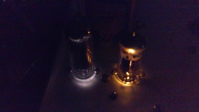
I wiped down and inserted the tubes into their respective sockets in the age-old practice of using a cloth for the procedure so as not to touch the glass envelope. Some of the printing on the Mullard 6EW6 was flaking off and I didn't see but a few ink specs on the cloth. The name and number are still clearly visible. The 0A2 could barely be read and the manufacturer isn't known. There wasn't anything else left but the ghost of the tube's number and "USA" on the glass. Could have been any of the American manufacturers. I'm looking for one where the model and USA are printed near the top of the tube. This tube reaches 109°F at the dome using a handheld laser pointer infrared temperature sensor at a distance of 8 inches. The 6EW6 checked in at 160°F.
Still out of it's chassis as the SWR circuit has some work left to be done, I plugged it in and turned on the timer to Visual. The original 0A2 (Zero-A-Two) gas discharge regulator tube on the left does work as does the 6EW6. I did not have a way to test this tube and now that I have seen it, it doesn't glow a bright violet like it had some time back. At lease it seemed to be a brighter violet then. Now it's a pleasant pale violet.
I did not test the 6EW6 in the tube checker since I need to repair that first. But, after getting the neon glow lamps yesterday I went through a rather lengthy process of trying to verify they were actually 5AG-A lamps. I'm still not convinced since they have a white dot that the 5AG uses, not a red dot the 5AG-A uses according to GE's Glow Lamp Manual. Could the color of the dot be decided on by the manufacturer and not an industry standard? I wasn't going to find that out any time soon so I decided to go for broke and give it a try.
The first test yielded a 04:22 (mm:ss) overshoot of the FCC required ten minute call sign announcement rule. Not bad for a first test of the timer. Of course every part but the transformer and tubes have been replaced so it would naturally have to be recalibrated. The potentiometers had not been adjusted from their original setting. I can't say when they were last set but it is possible they haven't been touched in the 47 years since it was built. I hadn't even checked them on the scope for linearity or noise.
After adjusting the Fine pot to the center position of its sweep up from where it originally was set, I set the Coarse pot down then hit the reset button and ran another test. It overshot the mark by a little over two minutes.
Leaving the Fine adjustment in the center, I tried again to get the timer to trigger inside of a minute. It overshot the mark by just over a minute. The next attempt was 32 seconds short. AHA! I'm getting closer!
Using my Power Director software and an old 2MP autofocus webcam I found in the junk box, I was able to record the tests to within a second or two accuracy. I started the timer by pressing the reset button about one second after starting the video capture.
I tried again to get the Coarse adjustment even closer. Upon the sixth attempt, the timer triggered at 09:45. I think that's close enough as I'd like to have that extra fifteen seconds to perform the call sign announcement. I'll leave it set to that.
I tested the Sylvania 0A2 I acquired and the timer seems to trigger earlier. I'll work with this some other time. Right now, I'm more concerned with the higher voltages at various test points than I should be getting according to the schematic.
For now, this concludes the timer portion of the SB-630 restoration project. I'll get back to the Numechron shortly.
73 for now!
__________________________________________


The Numechron -- This little gem has quite a following. It's look began in the 1930's by a company called Pennwood. Take a look at this nice write-up on the clocks: http://www.uv201.com/Clock_Pages/pennwood.htm
After taking mine apart and inspecting it, there seemed to be very little wear. Just a bit of dried up grease and dirt caught in the crevices of the drums where the copper springs travel along. Cleaning the numbered facets of each drum took a bit of patience and careful control with the cotton swabs. Since I was using Super Clean to do much of the cleaning, and it was plastic safe for automobiles, I used it on the drums. Careful wiping motions were needed around the numbers lest they dissolve in the cleaner yielded the best result. I wasn't able to get to all of the blank space inside number like 2, 7, 4 and so on. You really don't notice it unless you're looking. There is a seller on ebay that has a renumbering kit. It's basically a strip of adhesive tape with the numbers on it for each drum. Pennwood actually printed the number on it with real ink. So if the were in poor shape, I can at least use a decal/sticker to recreate the numbers if needed. There is a slight yellowing of the plastic around part of the drums. This is normal for as it had been exposed to fluorescent lighting.
Cleaning the inside of the drums took a bit of effort to get the old grease grime out of the crevices. There wasn't any lubricant on the axle shafts so that will be taken care of upon reassembly. Removing the copper springs isn't bad. Just loosen the screw that holds it and carefully take the tension off. Don't let the screw fly out from under the screw driver. Best to use a magnetic driver. Ask me why I know. ;-)
So a little cleaner to wipe down the inside of the drums, the frames and swabbed the springs. Now it was time to figure out how to fix the Minute drum. As I mentioned previously, it won't go to Zero from Fifty Nine completely. The picture showed one of the tips was chipped. Using some Gorilla Super Glue I built up the material to shape into a new tip. I've done something like this before in my model railroading experiences but only a couple of times. I debated on using the Gel or go with a quick setting formula. I chose the quick setting stuff and after a couple of hours, had enough of a dome to work with. I let it sit overnight whilst finishing the timer and SWR bridge rework to allow it to fully cure.
While shaping the glue dome I noticed the stuff isn't hard like Crazy Glue. Instead it feels fairly solid and cuts well with an X-Acto knife. Filing was too difficult hence the knife. After assembling the clock movement, I ran a couple of tests manually working the mechanism. Discovered it was catching on the reshaped glue dome and used the knife again to trim the height off. I put it back together and got that problem taken care of. Now it was time to take it apart one more time to lube each of the troughs the springs settle into holding the drum in place. I also lubed the drum shafts with Labelle 106 plastic safe grease with PTFE (I used this in the gear boxes of my model locomotives and know it's plastic safe.) Securing the motor was easy as there was some kind of settling from before that allowed me to simply tighten the screws holding it where it had been before. While running the clock, I noticed the minutes would not turn fully to their positions. Watching the cam between the motor unit's drum and the minute drum with a magnifying glass, I could see it wasn't catching the cog deep enough and adjusted the motor's position to solve the problem. It was time to install this 47 year old clock on the chassis.

Mounting it was easy. After installing the threaded rods into the bottom of the clock base and threading the standoffs onto those, it was ready to be attached. Now I didn't have the "thick" washers the manual speaks of because Dad had used four rubber washers instead to mount the clock. This was to isolate the clock frame mounting posts dampening the noise of the motor through the chassis. I mounted it without the the washers and it was a bit loud for my tastes. As much as I like the sound of the clock running, it isn't as pleasant when emanating through the chassis. So I put in only two of the rubber washers and added two flat washers so the clock's mounting posts won't dig through the old rubber washers. The screws were snugged down but not tightened. Viewing the clock through the view slot allowed me to see how level the numbers were. After making adjustments the clock seemed ready for a long test run. The motor still doesn't sound off through the chassis even with the screws underneath in contact with the chassis. I did notice it runs a bit more quietly after oiling the output shaft bushing with Labelle 108 synthetic oil. Only two drops on each end of the shaft bushing were used. I have used this oil on the bushings on the motors in my model locomotives too.
So it sits now, in operational testing for the weekend for time accuracy of the clock and keeping the Call Sign Identify timer turned on as well. I tested the buzzer and it still works. Still scares the crap out of me. I might use new rubber washers to isolate it further from sounding through the chassis. Just can't stand it so it will remain in visual mode. The SWR circuit will be tested and compared to another SWR meter. Not having a Byrd meter will probably hurt in the end but if I get the same readings between what I do have I'll be happy. I'll be making up a couple of new patch cables to tie into my radio setup shortly.
The cover has some accumulated dirt on it and the paint isn't is the best shape. The paint is flaking off of the other cabinets and with the rough texture, will do the same thing. I'll be looking into refinishing all the covers and how to achieve the same texture and color. For now, it will remain untouched.
And finally, to wrap up the project I'll need to locate the window plate that fits in the viewing slot. I have it somewhere and will reattach it to finalize this project when I come across it.
One modification has come to mind. Lighting. I thought it a bit odd there wasn't a lamp to illuminate the meter or the clock. Then it hit me as to why: It would be on all the time and you would use up the bulb life in roughly 2000 to 3000 hours based on their specifications. There are 8760 hours in a standard year. Do the math: 8760/3000=2.92 bulbs per year. Had this unit been running for the last 47 years Dad would have replaced the bulb 137 times. The cost would be more than acceptable and most any operator would have left it burned out after the first couple of replacements.
So why this lamp thing all of the sudden? I use an amber LED strip attached to the underside of a shelf my monitors sit on. This illuminates the keyboard and desktop surface as well as the faceplate of the Kenwood and the Behringer 502 mixer. I power them with an old Micronta (RS) regulated power supply I used to use with a CB back when I was a kid. I know what you're thinking. Why not use an LED to light up the meter and the clock with LEDs? Sure. Sounds good but inaccurate to the period. LEDs were available in 1970 but not used widely due to various reliability factors as they were hand-built. But with so many choices of LEDs out there, I wouldn't be surprised if I found one that just about had the same color temperature as the #47 bulb had. That or use amber lighting for low light viewing.
This has been a fun first project. I've enjoyed reworking this vintage piece of equipment back into operation and will be using it on my newer Kenwood TS-450S/AT for now. When the SB-401 is restored, I'll move it over to service the original equipment it was designed for.
Thanks for joining me and hope you liked the read!
73!
Smitty
K4ACS
________________________________
I might change the resistor that keeps the alert lamps lit a bit longer. It's in original operating mode now and it's nice to have it working again the way it was designed.
I found the window that mounts to the back of the clock bezel. I'll clean that up and glue it back in place in the near future. When I get that done I'll snap off a pic.
That's it for now!
73!
_________________________________
If you are new to this blog post, please grab a cup of coffee and make yourself at home. If you are a returning reader, grab that cup of coffee over there and jump to the bottom of the page for the latest date heading.
These posts and updates are in Commentary-style. There aren't any step-by-step instructions to restoring this piece of equipment.
List of web sites parts were procured:
Digikey - discreet components
Mouser - discreet components
West Florida Components (ebay) - 5AG-A Neon glow lamp
Kimco Distributing (ebay) - Kester 44 Solder
Great Estate Electronics (ebay) - potentiometer nut, washer, lock-washer set
Local sources:
Nick's Trains - Labelle 106 and 108 synthetic lubricants
Carquest/Advance Auto Parts - Quick Dry Electronics Cleaner
Thanks goes out to all the sellers! You've help make this restoration project a success!
Here's a partial list of sites or publications I use as my project resources:
http://www.radiomuseum.org/r/heath_station_console_sb_630_sb.html
http://www.heathkit-museum.com/hvmtest.shtml
http://www.uv201.com/Clock_Pages/pennwood.htm
http://www.transcendentsound.com/Tubes_and_Circuits_by_Bruce_Rozenblit.html
http://www.surplussales.com/
http://www.tedss.com/
http://www.k4eaa.com/parts.htm
http://www.ohio.edu/people/postr/bapix/capchkr2.htm
http://boatanchorpix.x10host.com/
http://mysite.du.edu/~etuttle/electron/elect27.htm
http://tubedata.milbert.com/?db=1
http://www.tubecollector.org/
http://antiqueradios.com/
https://www.nostalgickitscentral.com/heath/products/test.html
http://www.tubebooks.org/Books/Zucconi_probes.pdf
https://maritime.org/doc/neets/mod06.pdf
http://www.hobby-hour.com/electronics/resistorcalculator.php
Note: I found that Digikey's 5-band resistor calculator couldn't figure the value of a 22 Megohm 1% resistor banded with Red-Red-Black-Green-Brown. In the fourth band, there was no Green available so I hobby-hour.com got the task.
https://frank.pocnet.net/other/Mullard/MULLARD_Electronic_Counting_Circuits_Techniques_Devices_20160521-0002.pdf
https://frank.pocnet.net/other/Sylvania/Sylvania_Technical-Manual_1970.pdf
http://www.tiffe.de/roehren/neon.pdf
https://ia601205.us.archive.org/24/items/GE_Neon_Lamps_1965/GE%20Neon%20Lamps%201965.pdf
http://poynton.com/notes/units/index.html
This site helps with proper notation of symbols and SI units.
Thanks go out to the above resources without whom this project would not have been possible!
Heathkit SB-630
1968 Catalog Prices
Kit SB-630.....................$74.95
Since there are three independent circuits in the SB-630, I thought I would offer a BOM list for the timer and the SWR bridge as two lists. I'm not going to be using Phone Patch so I'm not going to be rebuilding that portion of the circuit.
I use both Mouser and Digikey to obtain parts. I'm not doing a price comparison only if I can get everything or the majority of everything from one or the other. For the more rare or esoteric parts, I use Surplus Sales of Nebraska, ebay, For those wanting a ready-made cart of the electronic components I'm using, please have a look at my Digikey cart. It has all the resistors and capacitors you'll need to rebuild the timer circuit. I have not included the parts for the SWR bridge. That is on a separate list below.
My Digikey Cart
http://www.digikey.com/short/3dzfw5
SWR Bridge
2 - Hughes Industries Germanium Diode - 1N191 from Electronic Expediters Inc.
1 - 56Ω 5% 1/2W Carbon Composition Resistor
1 - 100Ω 5% 1/2W Carbon Composition Resistor
I am fully aware that I'm no expert in the subject of restoration of vintage radio equipment so what I say and do here may conflict with your idea of what's "right". If you have a constructive comment, please, let's hear it. I am full-time employed with the odd side job now and then so updates may have time gaps between them. All I ask is please be patient.
Heathkit SB-630 Station Console
What is it?
This unit is actually part of a three-unit monitoring system for the SB series transmitter/receiver sets and transceiver units. Smaller single-purpose accessories may duplicate the functions combined in these pieces of equipment. The three units of the station monitoring system in reverse numerical order are as follows:

The SB-630 Station Console in the picture at left featured a forward and reflected power indicated with one meter and selected with a rotary switch; 24 hour Numechron "digital" clock movement; visual or visual/audible FCC 10 minute call ID reminder and a phone patch circuit.

The SB-620 Scanalyzer was an early type of pan-adapter driven by an IF signal port on the back of the receiver. This offered the operator a view of signals present around the operator's tuned frequency with a selectable 10kHz, 50kHz or up to 500kHz in variable bandwidth mode.

The SB-610 Monitor Scope was designed to monitor incoming and outgoing modulation. This helped operators from splattering outside his frequency requirements and improve his modulation quality while transmitting. It is capable of showing trapazoid geometry when used with an amplifier. It also offered the operator a way to monitor incoming signals for modulation quality as in RTTY operations as well.
I only own the SB-630 and it will be the first of six pieces to be restored. The unit is in good shape for it's age. My father built it as well as an SB-401/303 combination transceiver set with the SB-600 speaker. I have these as well as some of his test equipment that also need restoration. All of the pieces don't appear to need much cosmetically as none have been in any smoking environment where the tar and nicotine and carbon from the smoke settle, discolor and otherwise poison electronics. However, the paint is showing it's age with the typical flaking off the aluminum covers from high humidity.
A typical bad-cap replacement will be performed using new parts. Before that, the unit will be partially disassembled and cleaned up. Once the new parts have been installed it will be calibrated, aligned, and reassembled for testing. I fully expect to replace several parts as they are now in my age range. Fifty-plus. Hopefully I won't need as much in the next several years. ;-)
A little back history about my involvement...
I remember I was two when my Dad built a Heathkit GR-180 color television. I couldn't wait to play with the big box it came in and did so for quite a while until it just wasn't a box any longer. When he finished with it and calibrated everything, we sat back and watched our first color TV. As the years went by I would turn the TV on and still go watch for the orange glow of the heaters in the tubes and knew there was something special going on. From those early years, I was fascinated with electronics, computers (Hollerith card era) and other mechanical things that had gears, chains, linkages, pulleys, belts, knobs, and wires not to mention lights. I watched him build the SB-401/303 (solid state receiver) series transmitter/receiver pair as well as the station console and the speaker.
Though he is not active in amateur radio any longer, of the items I have from him are the aforementioned radio units, an Icom IC-745 (non-working), a Paco S-55 oscilloscope, Heathkit TC-2 Tube Checker (as opposed to true 'testing' of the tubes like a Hikoc can) and quite by accident, his old Heathkit IG-102 RF Signal Generator I picked up at the local RARS hamfest this year (2017). I needed an RF signal generator and wanted the one he had used to calibrate many things over the years with including the radio set.
I had bought my own SB-401/301/600 set with the intention of restoring it until my Dad offered his to me. Now I'm interested in restoring both sets. Other pieces of equipment I am looking to get hold of is a VTVM (bought an IM-13 May 12, 2017) and a capacitor checker by Heathkit, of course. For now, I can get away with a DMM but when it comes time to calibrate everything, a VTVM will be the meter of choice.
Which brings us forward to 2013 where I finally decided to get my General Class license. As my reward for passing the "grade", I bought my first working HF rig at the hamfest in Huntsville, AL. A Kenwood TS-450S/AT now sits on my desk to the right of my keyboard as I write this.
Now in 2017 I feel I have paid enough to the School of Hard Knocks to really want to get back to my real interests in electronics and enjoy a hobby again. Call me a Radio Angler or a Signal Wrangler, if you prefer. Any time I get a chance to listen I fish for radio signals while sometimes wrangling station signals to pull them out of the noise floor.
After several weeks of on and off researching antique radio forums, component substitutions, test equipment, history, and performance specs, I think I've got enough info to begin the restoration process. Though this is the simplest piece of equipment I have, I feel it is a good re-introduction to the technology and design of the time. So without further adieu, let's begin...
The SB-630 Project Start
I started out taking a lot of pictures after getting the chassis out of the cover to document as much of the condition and of the actual connections themselves as I could. It would also serve as a visual reference should an assembly manual not be available in the next few weeks. A few are shown below.

Inspection
Removing the screws and pulling the chassis out now done, the naked unit sits on the desk waiting, in all it's grimy, dusty glory.


Cleaning
When considering cleaning of the chassis, I would cringe every time I read that somebody has used or recommended water, steam cleaning or the dreaded dishwasher. I know some have used these methods and claim they don't have any issues. I wonder if further inspection of those units now would yield corrosion and oxidation beyond what they originally started with before the cleansing. Since water is the universal solvent, water ingress of variable mica capacitors can leave residues from the water impurities. Water corrodes wiring by capillary action from the point the insulation ends up the wire under the insulation. There is no 'seal' even with heat shrink tubing. And forget about any textile covered wiring. No. Water isn't a good idea unless all wiring and parts have been removed where impurities will remain. A tunable radio is more desirable than one that now requires more work because using the water changed things.


I saw one restored radio where some kind of liquid electrical tape was used on each connecting point to try and seal up the exposed wire where the insulation ended. Looked kind of weird and maybe more trouble than it's worth when a repair is required but if that's what it took to protect the wiring in the humidity of deep south Georgia in August, then more power to them.
SWR Bridge
Figuring there are carbon composite resistors inside the bridge, I decided to rebuild it with new components. First, I had to remove the cover which would allow access to the two wires running through the side of the box to the meter circuit. Two disc capacitors, two 1/2 watt resistors and two germanium diodes are all the electronics making up the device. Germanium diodes were very common in those days and had excellent sensitivity. Today, a Schottky signal diode (named after German physicist Walter H. Schottky - Schottky_diode) would most likely be used instead.


After disconnecting the wires, I could take it off the chassis and disconnect the components for testing without having to work with the main chassis.
 As you can see, the resistor on the output side of the bridge read 57.9Ω. The value should be 56Ω. For a carbon composite resistor, it is within its Gold Band (5%) tolerance by .9Ω.
Since I'm not trying for a gold medal in a concourse restoration of
vintage equipment, I'm not concerned with what was used in this device.
I'm more concerned with quality and accuracy of said device. We all
know Heath's kits are only as good as the parts and their builders, but
where improvements can be made economically and have it perform better,
I'm for it.
As you can see, the resistor on the output side of the bridge read 57.9Ω. The value should be 56Ω. For a carbon composite resistor, it is within its Gold Band (5%) tolerance by .9Ω.
Since I'm not trying for a gold medal in a concourse restoration of
vintage equipment, I'm not concerned with what was used in this device.
I'm more concerned with quality and accuracy of said device. We all
know Heath's kits are only as good as the parts and their builders, but
where improvements can be made economically and have it perform better,
I'm for it.
The next picture to the right shows the input port resistor at 109.8Ω. This is banded as a 100Ω, 5% tolerance resistor. This is well outside its tolerances so this will be replaced as well.
Now one of the pieces of test equipment I really wanted to get my hands on is a Heathkit IT-11 or IT-28 capacitor checker. The only difference I could see between them was the IT-28 could be configured for 240 volt mains like Europe and many other countries use. Other than that, I prefer the IT-11's two-tone grey over the brown. With this I can test not just capacitors but also their leakage point. Disc caps are cheap and I'd just replace them if they look bad. But electrolytic, mica, poly-types and paper types can show they work just fine at lower voltages. The IT-11 and IT-28 can charge a cap up to 600V so you can find their point of failure up to a 600V value. Mica and poly-types are very durable but can fail due to perforation of the dielectric material or mechanical damage. Electrolytic types fail mainly from drying out if wet types or the dielectric is physically damaged from heat stress like the paper types. There is the process of re-forming a capacitor but it can still suffer from perforation and you might not know it until it takes out an expensive transformer. If there are capacitors in there made as a silver mica, you also have the added problem of whiskers growing through the dielectric and shorting out internally through the adjacent dielectric layer.
Stay tuned for further updates!
Back again today having had some time to contemplate the SWR bridge and other items. After testing several of the old carbon composition resistors in the timer circuit and all, so far, are out of spec by any amount, I've come to the conclusion they all need to be replaced. If the rest test as bad, then what to replace them with? In the bridge you can't use any resistor that has inductance. This rules out any kind of resistor that is constructed with a wire-wound construction or layered on a ceramic rod, coated with resistor material and helical cut to fine tune the resistance value. That helical cut is indeed a coil. This rules out Carbon Film, Metal Film, Metal Oxide, and Wire-wound. So far, I have not found any manufacturer as yet that produces a resistor that can exactly replace a carbon composition resistor.
So now the question is, what type of resistor is used in modern radio RF circuits? That's right! Surface mount! Those tiny little chip type resistors that require a macroscope (for everyone else ) or a microscope (for those of us using reading glasses). One of those USB microscope cameras sounds like a good idea right about now. Wished I hadn't passed up that deal at the hamfest last month.
As for the carbon compositions.....I've read that the Allan Bradley's were top-notch MIL-spec and tedss.com has them. Knowing that the carbon comp's all rise in value over time with heat stresses and moisture absorption through the junction of the leads and case joint, it would stand to reason that even stored and unused, they can be compromised. So I should ask the question, how exact am I willing to attempt to get the SWR meter to read? If it's to be used, it should be accurate right? I'm learning that accuracy isn't always attainable due to the rules of diminishing returns.
I discovered an open rectifier (D5 on the schematic) so both will be replaced with Vishay 1N4007-E3/54 pieces.
New electrolytic caps (C26 and C27) have been procured early in the hopes that the resistors were okay. But it wasn't to be that easy. "Nothing's ever easy." -Zeddicus Zu'l Zorander

I also snagged a NOS Sylvania OA2 at the hamfest last month (April).

In the meantime I am putting together an extended parts list for this unit for a complete restoration of the SWR circuit. Since I will not be using Phone Patch, I won't be replacing any of those parts. A note to any future owner will be taped to the chassis to document the changes and omissions. The parts lists will be saved in my Digikey and Mouser accounts for future reference. If nothing else, it'll be restored to original operating condition even if period tech can't be improved upon with modern manufacture.
May 07, 2017 Late update!
Actually a very early morning update.More testing revealed all remaining resistors are out of spec. So the decision was made to replace all fifteen resistors in the timer circuit plus the two in the SWR bridge. I decided to go with Metal Film from Vishay as they are not part of an RF circuit. Most are 1% with 100PPM/C The single 22k 2W resistor (R38) might be better suited as a Metal Oxide but I'm not sure. I bought both in case I change my mind.
I added two sets of capacitors and two sets of carbon composition resistors for the SWR bridge (is it really a bridge or a resistive mismatch detector?) so I could play with the values to see if there is a difference between the stock set up and changing them. Heathkit shows one 56 and one 100 Ohm resistor used but both capacitors are .005uF. I've built a few SWR "bridges" using two 100 Ohm resistors and two .001 caps. Not sure why Heathkit engineers designed it this way. I would love to be able to talk to one about this. The circuit appears inherently imbalanced thus making a measurement really inaccurate thus increasing the stigma about lousy SWR readings on Heathkit meters. Maybe I'm just missing something here. Or maybe the imbalance accentuates the reflected power since very specific measurements to where these components are attached on the rods.
So my order to Mouser has gone in and now I wait. I saved the cart as a project and will tweak it a little bit for the bridge in case anyone wants to get a list of the resistors to purchase for their own resto-mod.
Until next time! 73!
Smitty
___________________________________
May 12, 2017 - Update
Dayton Hamvention - May 19-21, 2017 !!! Watch W5KUB's live stream at the show!!!http://www.w5kub.com/
SB-630
I received my order from Mouser and checked in the manifest. I also received the capacitor order from Digikey for the SB-301. I'm in the middle of cleaning out and relabeling an old steel cabinet with 60 plastic box type drawers for the resistors. I have two but a few of the little plastic compartments are missing and decades of dirt, dust, and other unidentifiable things have stuck to it. So the drawers were emptied of useless stuff, and useful stuff was transferred to the other one in preparation for a trip through the dishwasher. The drawers at least. I'll just wipe down the cabinet with Super Clean and a damp cloth. I think I got these cabinets back in the late 70's as either a birthday or Christmas gift. I do remember I got them before Skylab came out of orbit and burned up. I ordered a new cabinet (sadly it's plastic) that is a tad wider and not as tall but still has 60 drawers I'll use for the capacitors. That one should be ready for pick up in a few days.
As for the chassis, I haven't yet started cleaning it as I want to be prepared with all the parts I'm going to replace. Namely the carbon composition resistors and the two Mallory 100uF/200V electrolytic's. Though I am using a comment style of project reporting, I hope it will be easier to follow the major work going on with this project.
_________________________________________
May 19, 2017
Had to put the SB-630 to the side as I prepare for one of those "odd" jobs on the side I have now and then to build a batch of office PC's. Once these are completed, I can return to work on the station console. So for now, I'll most likely update my main blog featuring other things from my shack.73!
_________________________________________
May 28, 2017
Doesn't seem like nine days since I last worked on the station console so let's get restarted, shall we?


I wasn't planning on removing the face plate but the thought that I might not get a chance to do this again loomed over me. I decided to do it so I could clean it up and scan it to get a pristine image of the face plate for future use.
Removing the knobs proved difficult only because I couldn't find my SAE Allen wrench set. When I did, it didn't have the 5/64ths size. So I picked up a set by Husky (my preferred brand) from the Depot on my way to church. On the way home, I needed cotton swabs, flat washers and rubber washers. Well, I got the cotton swabs! Yay! But I forgot both the rubber and 1/2" flat washers. Booo! The rubber washers are used for the clock mounting to offer some noise and vibration isolation from the chassis. Without them, the motor noise would translate through the chassis making the motor and gears much louder than acceptable. The flats are for the mounting nuts for the panel controls as three switches are missing them. Not sure if the Depot will have them but I will check around. If I can't locate any, I'll put the ones I have on the rotary switches first. I don't anticipate using the Phone Patch but I'll service it anyway. Once the knobs were removed I remembered the power knob for the alert timer didn't seem to work right. Removing the knob revealed the problem. The shaft coupling sleeve had split and tightening the set screw will not have any real effect. Now I looked at all the shafts on the controls and noticed none had an index flat on them. Sooooo, I'll be carefully modifying the shafts of the rotary switches to give the set screw a better seat. The variables don't need much torque to use but the rotaries can stress the old plastic more if the screws have to be tighter to prevent slippage.
Removing the nuts attaching control wires for the SWR/PWR meter was difficult. I needed something the hold the base nut in place while loosening the nut that attached the wires to it. Once done I could tell there is something on the threads. Corrosion or thread-locker. I can't tell. I will find my Dremel and the wire wheel to clean them and the lugs. Removed the meter and cleaned it up too. It came out looking practically new using the damp cloth with soap and water then wiping it down with plain water on a cloth. To get into the crevices of the details of the meter face was easily done with a cotton swap. Just the brass terminal studs need to be cleaned now.
 |
| A number "8" with "JPM" inside a circle mean anything to anyone? I think this is likely an inspector's stamp. |
 |
| Blackened tips of studs and whitish crud on the threads. Notice the "040"? The whole number is 040170. Most likely a date code which isn't coded at all. Just April 1, 1970 or 4 of January, 1970, depending on where it was manufactured and/or which date format was used. Either way this dates the kit and puts it about a year later than I thought Dad had built it. |

Removing the pilot lamp was interesting. It took a bit more finesse than expected to get to the lead on the power switch for the timer. Trying to get the right angle for the solder sucker was a bit of a trick without burning through insulation elsewhere. A small puff of smoke and the telltale acrid odor proved I needed more finesse. Fortunately it didn't burn completely through the insulation. Removing the pilot lamp was a milestone in the project. I could now remove the face plate.
The push-nuts holding the Heathkit badge and meter bezel weren't hard to get off. The clock bezel and chromed metal Heathkit badge were removed and set aside for cleaning. The badge really didn't need more than a cotton swab run through the channels of the casting. The bezel was cleaned with the soap and water mix on a damp cloth then wiped with a plain water damp cloth.
 |
| Interesting reveal shows this was sitting on a grid during painting. |

The face plate showed a little bit of dirt that came off easily and brightened the silk screening a tad. I probably could do more but don't want to risk removing any of that to make it perfectly new looking. Careful wiping with with a damped cloth with soap and water cleaned up the face plate well. A wipe down with plain water damp cloth finished the cleaning process. The crinkle finish remained as did the silk screening. After the cleaning I fired up the scanner and scanned it in several different modes. I'll go through them later for a more detailed evaluation but a quick look appears they are good quality images. With the right software, one can at least be used as a template to make a vinyl over lay in case the worst happens. If that happens, I'll either opt for a Collins-like color scheme with a darker face plate and lighter cabinet or go the Hammarlund route and go all black with white lettering. I wouldn't do that with these pieces my Dad owned. The SB-401/301/600 set I bought would be a modified color scheme though. They were owned by a smoker and the paint is almost completely flaked off the cabinets down to the bare aluminum. Just handling them has left a trail of green paint flakes. Not really looking forward to cleaning those pieces just yet.
Maybe I'll polish the cabinets and seal the aluminum (aluminium for our British friends) like mag wheels on a hot rod with a Candy Apple Red face plate with larger white lettering, black knobs with polished gold centers and gold anodized knob skirts just for the shock value. :-p The face plates are still okay but I'm not sure what will happen when I try to clean them, hence the need to scan the good ones from my Dad's set.
 |
| Gray scale scan for the silkscreen detail using the holes as locators. The scanner bed cover was removed thus no white background except for a grey cloth. The face plate has a slight bow to it and I had to weigh it down for it to sit flat on the glass. The cloth hides the writing on the Porter-Cable battery used as the weight. |
Component Removal Begins!
 |
| Rest in peace ol' Mallory's. You've performed admirably. |


As you can see in the photos, one showed a forward resistance of 700Ω while the other shows 688Ω so no open rectifier. Hmmm. Testing in-circuit shouldn't have given me that open reading and I later discovered a problem with my Common probe so I replaced it with another. I tested them in reverse as well just to be sure and I got nothing so these are good but I consider them mismatched. I'll save them for another project. I'll replace these 57-27 SENS 600V 1A rectifiers with a couple of 1N4007 1000V 1A pieces I already have.

So this concludes today's work. It is now 0100, May 29, 2017. Remember our fallen brave men and women on this Memorial Day whom gave their lives to protect the freedom's they fought for that we hold dear no matter which war they fought in.
_________________________________________
June 3, 2017 - Cleaning Stage
So I took some time off of the "odd-job" of PC work to get some work done on the SB-630. I finally remembered to order the capacitors after sorting the resistors and noticing the capacitors were still missing.I started cleaning the top of the chassis without removing all of the parts except the clock. I wasn't planning on doing a complete disassembly down to the individual parts and reassemble it as a new kit. Originally it was just a cap change. Next the resistors tested faulty and while I'm so deep into this I decided to get as much of the top deck cleared off to clean it. I wasn't going to desolder the transformer so I unbolted it and raised it with what little slack there was in the wires to get some cotton swabs underneath to clean under it. The area was pretty clean to start with and after cleaning around it, I mounted it back in place to prevent any undue stress on the wires. Breaking those off won't be catastrophic but would be a major pain to repair. Unwinding and rewinding transformers isn't at all fun.
Anyway, the cleaning process isn't hard. But I am finding out that Super Clean from Castrol may not be the best at cutting the dirt. That or the exposed part of the chassis has some other kind of deterioration that needs to be addressed. What's happening? After an initial rubbing off of the dirt with a dry rag, the dirt is coming off so thick with the Super Clean that it's leaving a residual layer behind. After repeated cleaning using clean spots on the rag, the residue remains. So is it a residue from the cleaner or a quick form of oxidation of the surface? I'm also noticing a distinct line of "pristine" surface delineated by the SWR bridge box and it looks a lot like the surface underneath the transformer. It's quite a bit more shiny than the long-term exposed surface. So the next step will be trying out some Duragloss 821 - All Wheel Cleaner if I can find locally. Otherwise I'll use the Eagle One brand of the same. I should follow it up with a protectant if I do go this route entirely.
Updated note: Wasn't able to find either wheel cleaner but the XYL told me she had some from Meguiar's in the car-care box. I also found Meguiar's Step 2 Cleaner Polish. Used some of that to work on the corroded spots. It also shined up the aluminum quite a bit. I did do some general area cleaning with the polish too see how shiny it would turn out. The chassis had a nice shiny sheen to it but a bit too bright for my tastes. To dull it back down to the original tone I used the wheel cleaner. Once done I then applied Duragloss 101 Polish Cleaner to seal up the surfaces and it came out nicely.
 |  |
| Before | After initial cleaning |
 |
| Final cleanup after Duragloss 101 application |
 |
| This was the worst of the total dirt that came off the chassis from the first cleaning pass with Super Clean. I have two other panels that looked better with each pass but the streaks remained however faint. Time for a polish! |
 |
| Corrosion spots after initial cleaning |
The large one in the upper right corner of the photo above is a real mystery as to why it's so large. There was nothing there but the dirt and thus hidden. However, all of the spots have centers indicating an event that began the corrosion process. An old solder splatter that ate through a coating on the chassis perhaps?

Some would say I should have put it in the dishwasher and be done with it. Like I said in my earlier posting, dishwasher safe, it isn't. It might clean it quickly but only if I completely disassembled it to a bare chassis preventing any water intrusion to where water should never be.
Before using the metal polish, I' shot the tube sockets with some electronic cleaner. DeOxit isn't available locally but CRC and Carquest QD Electronic Cleaner (made by CRC) are available at my local Carquest/Advance Auto Parts stores. I have some of the Archer cleaner left and will use that up first. I also have some of the Archer tuner cleaner with lube I'll use on the rotary switches once I find it somewhere in the closet.
 | |||
| Part Number: 1040 |
Until next time! 73!
_______________________________________
June 10, 2017
Good afternoon! I was up late last night desoldering and removing the components that will be replaced. Let me tell you, it is far easier to build than to un-build. Here's why: All of the solder joints kept clogging up my solder sucker. This is primarily because the lugs are large, have large holes with, and in some cases, several wires run through them. This traps a lot of solder. The lugs with only one wire or lead through them take less solder but more than my spring-action Soldapullt Model SS750 can get in a single shot. So I will be looking to another solution that will cost around $109 on ebay. Until then, this thirty year old solder sucker will get a new tip. I'm able to use it as old as it is by cleaning out the cylinder and o-ring groove in the piston of stray solder. Before reassembly, I lubricate the o-ring with silicone paste. Edsyn makes this model in black as the SS750LS (Low Static) version. They also manufacture desoldering stations starting at $690.
Backwards? https://www.youtube.com/watch?v=BnR_DLd1PDI
Which capacitor to use? https://www.youtube.com/watch?v=67M7fsbLUIU
If I ever do have the opportunity to purchase an IT-11 or IT-28, I will then have the ability to test any of my old capacitors completely. Since these checkers have up to 600V available to test leakage with I can rate the capacitors and allocate them to a better suited less critical circuit without tossing it out until it is completely useless.
 |
| A pile of parts comprising 95% of the timer circuit |
 |
| At the stage of Prewired Chassis. Note that Relay K is attached but out of the way to get to the Germanium diode and installation of the Orange Drop where a resin capacitor once was. |
You can also see the 3/16 amp slow-blow mains fuse in the lower center, the alert relay (loose) near top center and that scary buzzer bolted there to the right of middle center. Let me tell you, that thing still works. Glad I can turn it off. I have to get a better solution to that thing like activate a player with the first word of James Brown's "I feel good" piece. Maybe not. That scream is worse. Only thing I can figure why it's a buzzer like that is to wake up the operator who fell asleep during a late night QSO!
Late evening update: It appears my B&K 1570A scope is having issues not the least of which are the missing probes. I'm sure there are bad caps in this one too considering its age. I wound up just touching one lead of the capacitor to the center conductor of Channel 1 and a ground lead to the other. I wasn't able to see with clarity, the same waveform that Paul of Mr. Carlson's Lab saw on his Tek 547. My scope will run 5mV/Div but the image is so blurry I could only just make out a somewhat defined waveform with the Orange Drops connected a certain way. When reversed, the waveform was just a faint blurry band. After doing this with a few more caps I am certain the better defined blurry waveform meant the probe input was connected to the outer shell thus registering my body as an "antenna" signal source. After marking the two, I decided to call it quits for the night and get some sleep.
Until next time! 73!
___________________________________________
June 11, 2017
In the home stretch as parts installation is mostly complete. I had to go through the assembly process from the start to ensure There weren't any parts or connections that I had to remove getting missed. It also gave me an opportunity to experience the process of assembly once again. Checking each and every step makes this time consuming but I wanted it done according to the manual instead of just jumping around. Now the manual appears to jump around too but it does so in a planned way to layer parts installation. One of the nice things about Heath kits are that you work primarily on one side of the chassis at a time. You're not constantly flipping it over back and forth for each wire passing through a grommet. "Twist the two black wires from transformer T1 and insert them into grommet F. These will be connected later." And thus you remain on the top side of the chassis.


 |
| Almost done! |
I was installing R28, a 1 kilohm resistor and broke off the neon glow lamp at the base when my iron slipped. I was pretty angry at myself realizing this whole project has been derailed for the time being.
The glow lamp in question is a 3AG-B that has specific voltage trigger range of 65-73 with a sustaining voltage range of 52-62 and a cutoff voltage of 50. These aren't made any longer but according to the GE Glow Lamp Manual published in 1965 (2nd Edition), the 5AG-A (NE-76) is within 3 volts of the same specification and was made by Chicago Miniature Lamps. An ebay seller has them in a lot of 20 since I was not able to find them on ChML's own website. Guess I'll be spending a little more than I thought.
So for now, the unit sits, waiting for the neon glow lamp until I can acquire one.
Until next time!
73!
_________________________________________
June 16, 2017
While I'm waiting for the 5AG-A neon glow lamp for the timer to arrive, I started disassembly of the Pennwood Numechron clock. It has a problem returning to Zero minutes at the end of every hour cycle. I wanted to see what might be causing it.


As you can see, it's in pieces on purpose. First off, the motor and gear assembly is completely sealed, which corroborates antique clock forums using this type of movement. I would need another one in bad condition to take apart and see how it was constructed. This one is relatively quiet during operation.
The clock movement proved easy to disassemble and there was no gunk where the copper tensioners held the drums in their positions. The tensioners are in good shape as are the runs where they ride on the drums. When I removed the drums and inspected them, it wasn't immediately apparent as to what could cause the Zero not to settle where it should until the first minute of the new hour. I also had an issue where the minute wasn't completely moving the next digit. Donning my glasses and using a magnifying glass to each drum I soon discovered the problem.

So that's where I'm at currently. I'll pick up some CA from a hobby shop (local shop, not a big chain) and try that.
Bye for now!
73!
__________________________________________
June 20, 2017
We have Glow!
The magic is happening again after all these years! This has been a fun and educational experience for me. Though I haven't built a Heathkit product (EK-1) since I was about six or seven, rebuilding this gave me some insight into many aspects of the technology of the period. Heathkit was resourceful to keep costs down and offer kits that performed well, most of the time.
I wiped down and inserted the tubes into their respective sockets in the age-old practice of using a cloth for the procedure so as not to touch the glass envelope. Some of the printing on the Mullard 6EW6 was flaking off and I didn't see but a few ink specs on the cloth. The name and number are still clearly visible. The 0A2 could barely be read and the manufacturer isn't known. There wasn't anything else left but the ghost of the tube's number and "USA" on the glass. Could have been any of the American manufacturers. I'm looking for one where the model and USA are printed near the top of the tube. This tube reaches 109°F at the dome using a handheld laser pointer infrared temperature sensor at a distance of 8 inches. The 6EW6 checked in at 160°F.
Still out of it's chassis as the SWR circuit has some work left to be done, I plugged it in and turned on the timer to Visual. The original 0A2 (Zero-A-Two) gas discharge regulator tube on the left does work as does the 6EW6. I did not have a way to test this tube and now that I have seen it, it doesn't glow a bright violet like it had some time back. At lease it seemed to be a brighter violet then. Now it's a pleasant pale violet.
I did not test the 6EW6 in the tube checker since I need to repair that first. But, after getting the neon glow lamps yesterday I went through a rather lengthy process of trying to verify they were actually 5AG-A lamps. I'm still not convinced since they have a white dot that the 5AG uses, not a red dot the 5AG-A uses according to GE's Glow Lamp Manual. Could the color of the dot be decided on by the manufacturer and not an industry standard? I wasn't going to find that out any time soon so I decided to go for broke and give it a try.
The first test yielded a 04:22 (mm:ss) overshoot of the FCC required ten minute call sign announcement rule. Not bad for a first test of the timer. Of course every part but the transformer and tubes have been replaced so it would naturally have to be recalibrated. The potentiometers had not been adjusted from their original setting. I can't say when they were last set but it is possible they haven't been touched in the 47 years since it was built. I hadn't even checked them on the scope for linearity or noise.
After adjusting the Fine pot to the center position of its sweep up from where it originally was set, I set the Coarse pot down then hit the reset button and ran another test. It overshot the mark by a little over two minutes.
Leaving the Fine adjustment in the center, I tried again to get the timer to trigger inside of a minute. It overshot the mark by just over a minute. The next attempt was 32 seconds short. AHA! I'm getting closer!
Using my Power Director software and an old 2MP autofocus webcam I found in the junk box, I was able to record the tests to within a second or two accuracy. I started the timer by pressing the reset button about one second after starting the video capture.
I tried again to get the Coarse adjustment even closer. Upon the sixth attempt, the timer triggered at 09:45. I think that's close enough as I'd like to have that extra fifteen seconds to perform the call sign announcement. I'll leave it set to that.
I tested the Sylvania 0A2 I acquired and the timer seems to trigger earlier. I'll work with this some other time. Right now, I'm more concerned with the higher voltages at various test points than I should be getting according to the schematic.
- At the junction of D4 and R38, it should be 330VDC. My DMM read 347VDC.
- At pin 5 of socket V2 (0A2) it reads 149VDC. Should read 150VDC.
- At pin 1 of socket V1 (6EW6) it reads 140VDC. Should be 130VDC.
- At pin 6 it reads at 171.4. Expected 160VDC.
- At pin 2 I get 3.36VDC. Expected 2.3VDC.
- Filament voltage is running at 7VAC. Expected 6.3.
For now, this concludes the timer portion of the SB-630 restoration project. I'll get back to the Numechron shortly.
73 for now!
__________________________________________
June 22, 2017
Well this project is moving along pretty well. I spent some time rebuilding the SWR bridge and finished it. The only thing left now is the Numechron. |
| New capacitors and carbon composition resistors installed with original Germanium diodes. Even though the diodes had a ten ohms difference between them, I decided to keep them in place. When I tested the Hughes Germanium diodes, I found two that had an ohm reading of 740. The other three weren't even close. The original diodes were 421 and 433 in-circuit. A little higher out of circuit but a spread of at least 10 ohms. So I decided not to use the Hughes Industry diode due to the higher resistance and perceived lower sensitivity. |


 |
| Ready for the cover and clock. |
The Numechron -- This little gem has quite a following. It's look began in the 1930's by a company called Pennwood. Take a look at this nice write-up on the clocks: http://www.uv201.com/Clock_Pages/pennwood.htm
After taking mine apart and inspecting it, there seemed to be very little wear. Just a bit of dried up grease and dirt caught in the crevices of the drums where the copper springs travel along. Cleaning the numbered facets of each drum took a bit of patience and careful control with the cotton swabs. Since I was using Super Clean to do much of the cleaning, and it was plastic safe for automobiles, I used it on the drums. Careful wiping motions were needed around the numbers lest they dissolve in the cleaner yielded the best result. I wasn't able to get to all of the blank space inside number like 2, 7, 4 and so on. You really don't notice it unless you're looking. There is a seller on ebay that has a renumbering kit. It's basically a strip of adhesive tape with the numbers on it for each drum. Pennwood actually printed the number on it with real ink. So if the were in poor shape, I can at least use a decal/sticker to recreate the numbers if needed. There is a slight yellowing of the plastic around part of the drums. This is normal for as it had been exposed to fluorescent lighting.
Cleaning the inside of the drums took a bit of effort to get the old grease grime out of the crevices. There wasn't any lubricant on the axle shafts so that will be taken care of upon reassembly. Removing the copper springs isn't bad. Just loosen the screw that holds it and carefully take the tension off. Don't let the screw fly out from under the screw driver. Best to use a magnetic driver. Ask me why I know. ;-)
So a little cleaner to wipe down the inside of the drums, the frames and swabbed the springs. Now it was time to figure out how to fix the Minute drum. As I mentioned previously, it won't go to Zero from Fifty Nine completely. The picture showed one of the tips was chipped. Using some Gorilla Super Glue I built up the material to shape into a new tip. I've done something like this before in my model railroading experiences but only a couple of times. I debated on using the Gel or go with a quick setting formula. I chose the quick setting stuff and after a couple of hours, had enough of a dome to work with. I let it sit overnight whilst finishing the timer and SWR bridge rework to allow it to fully cure.
 |
| As I hope you can see, I tried to replicate the cam. Hopefully this will work. |

 |
| In operation on Zulu (UTC) time. |
Mounting it was easy. After installing the threaded rods into the bottom of the clock base and threading the standoffs onto those, it was ready to be attached. Now I didn't have the "thick" washers the manual speaks of because Dad had used four rubber washers instead to mount the clock. This was to isolate the clock frame mounting posts dampening the noise of the motor through the chassis. I mounted it without the the washers and it was a bit loud for my tastes. As much as I like the sound of the clock running, it isn't as pleasant when emanating through the chassis. So I put in only two of the rubber washers and added two flat washers so the clock's mounting posts won't dig through the old rubber washers. The screws were snugged down but not tightened. Viewing the clock through the view slot allowed me to see how level the numbers were. After making adjustments the clock seemed ready for a long test run. The motor still doesn't sound off through the chassis even with the screws underneath in contact with the chassis. I did notice it runs a bit more quietly after oiling the output shaft bushing with Labelle 108 synthetic oil. Only two drops on each end of the shaft bushing were used. I have used this oil on the bushings on the motors in my model locomotives too.
So it sits now, in operational testing for the weekend for time accuracy of the clock and keeping the Call Sign Identify timer turned on as well. I tested the buzzer and it still works. Still scares the crap out of me. I might use new rubber washers to isolate it further from sounding through the chassis. Just can't stand it so it will remain in visual mode. The SWR circuit will be tested and compared to another SWR meter. Not having a Byrd meter will probably hurt in the end but if I get the same readings between what I do have I'll be happy. I'll be making up a couple of new patch cables to tie into my radio setup shortly.
The cover has some accumulated dirt on it and the paint isn't is the best shape. The paint is flaking off of the other cabinets and with the rough texture, will do the same thing. I'll be looking into refinishing all the covers and how to achieve the same texture and color. For now, it will remain untouched.
And finally, to wrap up the project I'll need to locate the window plate that fits in the viewing slot. I have it somewhere and will reattach it to finalize this project when I come across it.
One modification has come to mind. Lighting. I thought it a bit odd there wasn't a lamp to illuminate the meter or the clock. Then it hit me as to why: It would be on all the time and you would use up the bulb life in roughly 2000 to 3000 hours based on their specifications. There are 8760 hours in a standard year. Do the math: 8760/3000=2.92 bulbs per year. Had this unit been running for the last 47 years Dad would have replaced the bulb 137 times. The cost would be more than acceptable and most any operator would have left it burned out after the first couple of replacements.
So why this lamp thing all of the sudden? I use an amber LED strip attached to the underside of a shelf my monitors sit on. This illuminates the keyboard and desktop surface as well as the faceplate of the Kenwood and the Behringer 502 mixer. I power them with an old Micronta (RS) regulated power supply I used to use with a CB back when I was a kid. I know what you're thinking. Why not use an LED to light up the meter and the clock with LEDs? Sure. Sounds good but inaccurate to the period. LEDs were available in 1970 but not used widely due to various reliability factors as they were hand-built. But with so many choices of LEDs out there, I wouldn't be surprised if I found one that just about had the same color temperature as the #47 bulb had. That or use amber lighting for low light viewing.
 |
| My computer desk lighting |
This has been a fun first project. I've enjoyed reworking this vintage piece of equipment back into operation and will be using it on my newer Kenwood TS-450S/AT for now. When the SB-401 is restored, I'll move it over to service the original equipment it was designed for.
Thanks for joining me and hope you liked the read!
73!
Smitty
K4ACS
________________________________
July 30, 2017
Not quite The End it seems. The clock is still running and after having to reset it due to a power outage after some idiot trying to text and drive swerved and knocked down the utility pole our neighborhood is supplied through. Since then it's been running and is still inside of three seconds accuracy. The timer also works really well. Every 9 minutes and 45 seconds it sets off the IDENTIFY light. The buzzer works good too. Still think it works too good though. ;-)I might change the resistor that keeps the alert lamps lit a bit longer. It's in original operating mode now and it's nice to have it working again the way it was designed.
I found the window that mounts to the back of the clock bezel. I'll clean that up and glue it back in place in the near future. When I get that done I'll snap off a pic.
That's it for now!
73!
_________________________________
Comments
Post a Comment