Heathkit IG-102 Signal Generator
1968 Catalog Prices
Kit IG-102.....................$ 29.95
Assembled IGW-102..............$ 54.95
Berkley Physics Laboratory Version (IGW-102S)....$60.00
It's been April of 2017 since I got hold of this at the local hamfest. My Dad had one and I wanted one but did not know where his had gotten to. I have a bunch of his stuff in storage and will go through it when I can.
 | ||
| My IG-102 on the day I acquired it at RARSfest. |
If you want to jump to the latest post, click HERE.
So here's the rundown. Read my Welcome for a little background on my interest in Heath Company's kits. I'm not trying to relive my childhood, but rather get back to my first love. Electronics from when I was a kid. Discreet component designs, point-to-point wiring in most of them, vacuum tubes, analog meters and neon tubes were at their peak in the 1950's and early 60's until the transistor began to take over. From many accounts, 1980 was the official demise of the vacuum tube for consumer products. Most will argue an earlier date but given the fact that Kenwood and Yaesu were making solid state with tube-final hybrid transceivers then, it stands to reason that total abandonment of the tubes or valves had yet to occur.
So here I am at fifty-something and enjoying the rediscovery of my preferred era of electronics with high voltages, low currents and a fair share of central heating. All in all nothing beats that magic glow.
The IG-102
Sometime around 1965, I don't know exactly, the IG-102 was offered with a range of 100 kHz to 110 MHz. It uses two old style microphone connectors for the probe. One is for AF and the other for RF. When the modulator is set to INT, a 400 Hz tone is generated for use with detectors. An EXT modulated signal can be selected. It uses two electronic tubes, or valves, namely the 12AT7 and a 6AN8.From the manual...
The Heathkit Model IG-102 RF Signal Generator is an accurate and stable source of modulated or unmodulated RF (radio frequency) signals. Six over-lapping bands provide a wide range of frequencies for use in the AM, FM, TV, LW, and SW broadcast bands.
The RF frequency is indicated on a large dial scale that is accurate an deasy to read. Switch-type and continuously variable attenuators are used to obtain output signal levels that are suitable for most applications.
A built-in audion oscillator provides modulation of the RF signal, and serves as a conenient source of audio signal. The RF may also be modulated by an external audion signal.
To insure greater accuracy of the RF frequencies, the band switch and coil assembly has bee assembled and adjusted to precision standards at the factory. The completed Signal Generator can be calibrated without the need to expensive calibration equipment.
I found a copy of the assembly manual online somewhere a while back. It's a copy of a used manual complete with check marks. If you want a clean manual, head on to manualman.com. Easily he makes the best quality first-copy of original manuals anywhere. The only thing better is an original manual that never saw the light of day.
Until next time!
73!
___________________________________________
February 22, 2019
It has been a year and a half since I posted the above text. Things have gotten routine enough again so I can plan a little time for projects again. The IT-28 proved to be a failed restore-to-operation project unlike the SB-630, TC-2, and Astron RS-20S projects. I'm still having trouble identifying the cause of the out-of-whack- voltages. So I put that aside and will begin this project since I am in need of this tool for work on the radios I plan to repair.To begin with, I built a BOM for the capacitors on Digikey's website. I decided to check out justradios.com to see what they have available. Their prices are good and shipping quite reasonable. Since I'm rebuilding the oscillator circuit with new capacitors, I should also use new manufactured carbon composition resistors. No metal film or oxide allowed. There is one 2 watt metal oxide resistor in the power supply circuit but it won't affect the oscillator.
Bill Of Materials
Capacitors1x - .0047 uF at 630V Tubular Axial Film Cap (Part#472K630V)
1x - .022 uF at 630V Tubular Axial Film Cap (Part#223K630V)
1x - .05uF at 630V Tubular Axial Film Cap (Part#503K630V)
1x - .1 uF at 630V Tubular Axial Film Cap (Part#104K630V)
2x - 22 uF at 250V Axial E-Cap - Replaces the 20-20 µF dual electrolytic filter capacitor.
? - 22pF at 500V Radial Silver-Mica capacitor (22uuF in assembly manual)
Resistors
2x - 47 ohm 1/2W Premium Carbon Comp Resistor (1 pkg of 5)
1x - 390 ohm 1/2W Premium Carbon Comp Resistor (1 pkg of 5)
3x - 680 ohm 1/2W Premium Carbon Comp Resistor (1 pkg of 5)
1x - 10K ohm 1/2W Premium Carbon Comp Resistor (1 pkg of 5)
3x - 33K ohm 1/2W Premium Carbon Comp Resistor (1 pkg of 5)
1x - 56K ohm 1/2W Premium Carbon Comp Resistor (1 pkg of 5)
3x - 100K ohm 1/2W Premium Carbon Comp Resistor (1 pkg of 5)
The first number represents the number of parts in the circuit. This is why I also put in the (pkg of 5) notation. I usually buy more than needed of any value most often used. It saves on shipping when I run into something else that uses those values. Though I really like Digikey and their incredible selection, I'm more often these days a bit dry mouthed about the carbon composition resistor selection. I can get most but not the exact value the circuit calls for. When I do find them, they are more expensive than I'm willing to pay for new-old style manufactured components. So I've been leaning more on JustRadios for the vintage type stuff. So all of the parts listed above were procurred from Just Radios.
They have resistor kits based on pre or post - WWII components with values most often used. Need a 20µF capacitor instead of the newer 22µF version? They've got that. Their carbon composition resistor kits also come in pre and post - WWII component value kits.
The parts are on order and can start working on the unit next weekend (March 02, 2019), if all goes well.
73!
________________________________
February 25, 2019
The parts have been shipped according to an email I received today. Shouldn't be long before I see them here. I might have some time this coming weekend to begin desoldering joints. I also made note of the high voltage capacitors used as line surge filters. This was the practice back then but an X1Y2 safety capacitor is the preferred method. I bought several and are made for hot-neutral, hot-ground, and neutral-ground connections. These are also used in place of the old Metal Oxide Varistor (MOV) I used to use to make my own surge suppressors back in the '80s and '90s.
Sorry I don't any of the pics I took of it initially since the purchase. They have gone somewhere into the ether never to surface again. Sucks when you switch phones and realize there's something missing after you blow it away. My mistake was failing to ensure the photos on the phone had been transferred to the SD card before removal of the card.
More to come!
73!
________________________________
March 04, 2019
Good evening. It's 2245 here and I've finally removed the old "protection capacitors" replacing them with X1Y2 safety capacitors. I feel better but only a little. There's no fuse so I'll need to add one in the future like with the other projects. There's no reason not to use a fuse and every reason to install one.
Next on list was that big, dual capacitor to filter the rectified AC. The original is pictured below.
 |
| Astron huh? Where have I seen that name before I wonder? |


Now one thing's for sure, this won't ever work again as it measures only 30pF. It leaks DC voltage at below 9VDC and cannot be reformed. "Oh! You can reform it! Just stick it on an IT-28 at the lowest setting and bring it up slowly over a few days. That'll work, guaranteed! I do it all the time!" says the tech with no brain.
To that, I say hogwash. I noticed the center core of the capacitor could move when I wiggled the single lead a little. The seal is gone and thus the capacitor has dried up and contaminated with moisture from humidity in the air. No reforming possible unless I unwrap the whole thing, reapply electrolyte, wrap it back up and check it again. Nope. Not gonna happen. If anything, I would save it to gut and install a pair of new caps inside to preserve the old-school look of the rig. That may happen in the future if worth doing. Right now, I'm only interested in it operational value, not it's cosmetic accuracy.
So with that removed, I can install the two 22uF electrolytic capacitors OR install two 47uF E-CAPs. I will get more filtering with the larger value. The problem is, will I get better results down the circuit into the oscillator circuit? The point of diminishing returns looms near. I can do some more research on this and install the two E-CAPs I bought for this project until I can justify the cost and whether or not those 47uF E-CAPs aren't affecting the circuit with too much ESR.
When this unit was designed, it was done in a varied power grid of 105-125VAC and the manual states 105-125 VAC. My guess is that the grid system had a wide range and the designers had to make sure it would work in the lowest and highest voltages available. My voltage readings today are 125VAC at the wall according the DMM and the VTVM plugged into an isolation transformer. A variac plugged into a true isolation transformer would be ideal but I don't have a variac let alone a quality unit.
So next step is to install the two 20uF filter E-CAPs and test the power section.
73!
__________________________
March 6, 2019
Did a little bit of work tonight. Had a few other things today requiring attention but I was able to replace a few components in the secondary power supply circuit.
As mentioned in the last post, I've replaced C23 and C24 with X1Y2 safety capacitors. One did fail-short when I tested for the capacitance. It had a bubbled surface and not fail-open though I would have expected it to be a several pieces and burn marks if it did fail-open. So! Glad I didn't just plug it in to "see if it lights up." Yeah, I didn't ask for fire light.
Safety Note: Actually, I have a rule about vintage equipment. If I didn't see it work before, I'm not about to just plug it in and see if I get a pilot light. Too many out there don't know what they're doing and don't realize what can happen with a shorted tube or a tube that has equalized or even what a dried up electrolytic filter capacitor can do. It's risky to buy from ebay because the seller that didn't know anything about it just plugged it in and destroyed a restorable piece without knowing it. I cringe when I see descriptions like "Powered it on and it lights up." Idiots at work let me tell ya. Patience has limits. Not so with ignorance. Assuming the gun is loaded, assume the unit will catch fire. You may lose only a transformer made of unobtainium or you can lose your life. Be safe and be in the know about the equipment you are working on.
Back to the blog....
Having installed the two filter E-CAPS, C25A and B, as individual parts and rated 22uF / 250VDC @105C. I did reuse the silicon insulated tubing for the positive leads. The next piece to be replaced was the 2.2K (2200 ohm) 1 watt resistor. I opted for a 2 watt version knowing Heathkit did run some of their parts at their rated limits and sometimes beyond them in normal operation. The original carbon composition type was replaced with a metal oxide type. Even though the resistance material is helically trimmed to achieve its ohm value, it's not in an RF circuit and thus it's inductive properties aren't a factor.
The two ovals with numbers in them are voltage test points. The numbers are "loaded" values so the whole circuit needs to be working to achieve these values. Unloaded values aren't given. After I replaced the parts and switched it on, the point at which I should read 155VDC read 153VDC. Close enough. The 130VDC value could not be tested but unloaded it read 196VDC. That's just how it is without any load on it.
The filament supply circuit only had the pilot lamp connected and the voltage read 7.9VAC. Yes, they are powered with AC, in a signal generator, that has an oscillator, inside the same metal box. Yeah. I might change that but need to get this up and running right before modding it.
Speaking of mods....Many replace the old style Microphone connector with a BNC type. I have one probe with the Mic connector and alligator clips so I'll leave it for now. The EXT. MOD/AF connector on the left of the front panel should be changed to a BNC. We'll see.
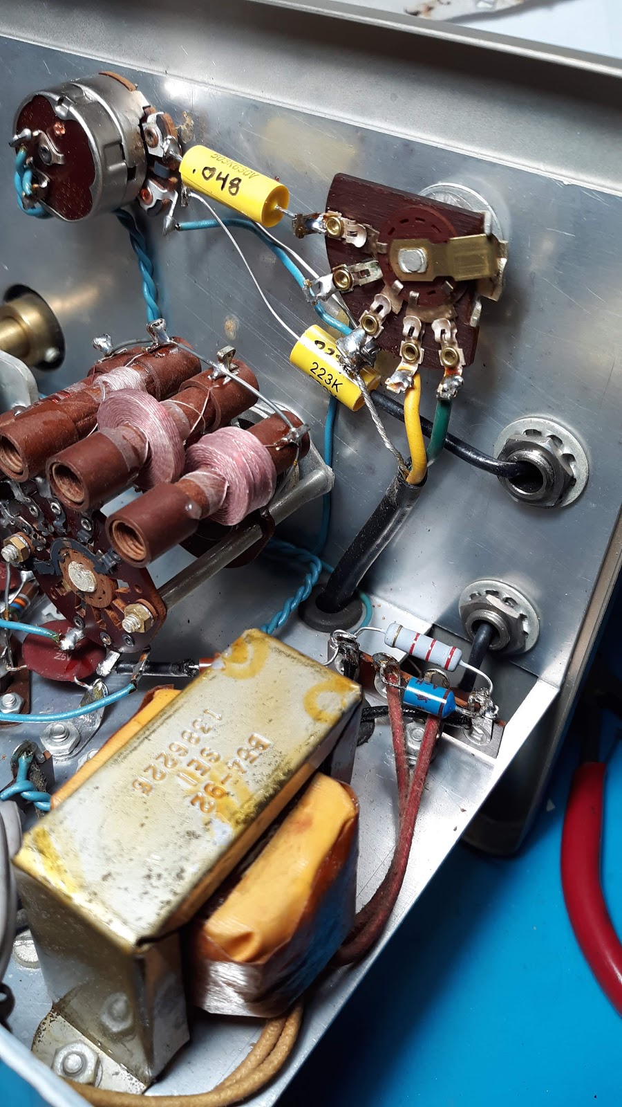
In the photo above I show the new 2.2K resistor in the center-right. Two yellow poly caps in the upper-center of the photo replaced two encapsulated paper-in-oil capacitors. They did test at the correct capacitance but could not do it above 17 volts. They pass waaaaaaaaaay too much DC so in other words, they leak badly. They were rated 200 and 400 volts. These caps are in the EXT. MOD/AF OUT circuit.
The value I wrote on these caps were read from a capacitance tester. The numbers printed on them encode their value so I chose to use a tester to verify which was which. Now I have their coding figured out so they will be easier to discern in the future.
That's it for this installment.
Good night!
73!
____________________________
March 7, 2019
Hello. Thanks for stopping in to check on the progress. Tonight I've replaced the resistors in the Coarse Attenuator circuit on the rotary selector. There are two 680 ohm (R13, R15), two 47 ohm (R14, R16) resistors plus the 3Kohm Fine Attenuator potentiometer (R12) and an AC coupling )or DC blocking) disc capacitor of .01uF (C22) to the RF Out connector.I have not yet replaced R11, another 680 ohm resistor connected between Grid 2 (pin 7) and the plate (pin 6).
At this point I'm just getting the easy-accessible items out of the way for now. The tube connections and components will prove to be a bit more challenging. I wanted to try my hand at in-chassis repair/rebuild instead of my usual teardown and rebuild I call a ReKit. Check out my TC2 project for that level of reconstruction.
That's it for now. Thanks for stopping in.
73!
________________________________
March 18, 2019
Tonight's work involved removing and replacing a resistor that is pretty much inaccessible without removing either the Band Switch or the tube socket (V1). I opted to de-solder connections to the socket instead. That way I wouldn't have to disturb the band coils much. |
| First, I had to remove this resistor/capacitor combination. It's a 22uuF Mica cap and a 33K ohm 1/2watt resistor. This runs from lug 7 on tube socket V1 to lug 2 on Tuning Capacitor G (S-2). |
 | |
| Now tube socket V1 is free from any wiring connections. The nuts and screws will be removed from V1 and the both ground lugs. |
 |
| Tube Socket V1 is removed as an assembly. A new 56K ohm resistor is installed and the socket can be reinstalled. |
 |
| It may be hard to see but there's a light brown irregular shape near the bottom lead. There is also blistering leading from it over the bottom right corner of the part in this view. It would appear this was a high voltage strike or overheating. Either way it tests as a 34pF (uuF) capacitor which is well outside the 5% of it's 22pF (uuF) construction. This will be replaced once another has been procured. |
Mica capacitors do not typically go bad unless they have been physically stressed, struck by a higher voltage than designed for, too much current or overheated. Hard to say about this one, When I tested it while still on the resistor, it tested 31pF after I noticed the blistering and discolored spot. It reads 34pF now and not much use in this circuit.
Socket V1 is back in the chassis and I'm making a BOM for some parts for the Halicrafters S-40B, now that I have a 5Y3 rectifier tube. I'll add this Mica cap to the next order of parts. Meanwhile, I still have a few more resistors and two encapsulated paper-in-oil (PIO?) capacitors to replace.
73!
_____________________________
March 20, 2019
Tonight's work began with the two remaining encapsulated capacitors with plastic cases. Testing after removal revealed C16, the .1uF was spot on but failed above 25V. C13, the .0047uF tested at .0052 and also failed to achieve its 200V rating down at 15V which is a disappointement as it was a Mylar type. Both of these leak DC voltage and are nothing more than non-functional museum pieces. These typically go bad mainly due to the acidic paper used back then which eventually deteriorates and becomes a resistor.I replaced R11, a 680 ohm 1/2 watt too. The original was in spec so I put it in the SAVE bin.
 |
| New tubular capacitors to replace failed Paper-In-Oil encapsulated pieces. The yellow one at the bottom was originally a "Mylar" type as described in the manual. This is nothing more than a Film type capacitor on today's parts lists that used DuPont's trademark name for the type. |
73!
_____________________________
April 3, 2019
Since my last update a lot has happened that got in the way of working on the IG-102. Last night I was able to complete the installation of the new parts and give it a basic calibration check. It's not great but the AM radio Zero Beat method does work and is pretty close to the dial after adjusting the trimmer capacitor. It had to be adjusted to nearly bottoming out but I think that will be okay.I have a PLJ-9VFD-A frequency counter. It's an open chassis firmware type from China. When the signal is strong enough, it does sample the signal solidly. The signal Generator isn't as "loud" as the Kenwood via a sampling box by CleanRF.com for use with an oscilloscope so I know I really need another counter. Might looking for one like the Heathkit IB-1101, IM-2410 or IM-2420, or even the IM-4100. If I can get the 9VFD-A to read the frequency more reliably, I'll try to use it. Otherwise I'll have to find a better solution soon. The little DSO I have does not calculate frequency so that was a dead end as well.
So far the drift from center is significant but not unexpected. I imagine the slugs in the band coils will need adjusting too. However, I am confident I would be able to use it at 455kHz to align the Halicrafters S-40B now that I have a rectifier tube for it. There was one other tube I needed but will have to check my notes to see which one. I have a box of tubes and may have one in there.
So far, this project has been pretty enjoyable to work on. Next is another attempt to start my Nixie Clock project. Any updates to the IG-102 will still be posted here and not in the Shack Happenings blog.
73!
____________________________
April 4, 2019
Tonight I wanted to get a handle on the output accuracy. I was able to get the PLJ-9VFD-A working. Turned out the hot lead is Black, not the red one. So after checking out its operation with a CleanRF sampler box on my Kenwood TS-450S/AT to check for accuracy and stability, I attached it to the IG-102 and my bench top supply set to 10VDC.After turning on the generator and letting it warm up for a few minutes, I knew something wasn't right. The generator was set to 100 KC but nothing was showing on the counter. I ran the dial up and didn't start to get a signal reading until right about 200 KCs. The instructions, translated from Chinese, didn't indicate a problem with 100 KCs. So there might be an omission, default setting I'm unaware of, or undocumented setting. I do have a Supeer A4 I was able to get a reading on below 200 KCs so I used that in the spreadsheet I plugged the numbers into
If you would like to view the files I share plus the test values, click here.
 |
| The IG-102 is set to 1MHz. 9VFD-A on the left and Supeer AV4 to the right. |
Now that I've got some test data, I can begin a plan of attack to get them closer to their dial settings. Hopefully I won't have such an offset. It's possible there's a feedback into itself at higher frequencies but all in all it seems to be stable regardless of the dial setting. Now the real work begins!
73!
_____________________
April 25, 2019
Good Evening! I completed the project and the IG-102 is ready for work.That being said here's what I did:
I recalculated the 2.2K ohm resistor in the B+ power supply. According to the math, in order to get 130VDC from a 155VAC source, I need a 1250 ohm 1 watt resistor. Heathkit specified a 2200 ohm 1 watt piece and I was a bit stumped as to why I was getting 196VDC. I should have gotten less. Well, the oscilloscope showed a bit more ripple than what I expected to see with a pair of 22uF e-caps even if rated at 250V. I took out the caps and installed two new ones and got the same result. Now my attention turned to the rectifier. I was getting 19 megohms in one direction and 1.2 in the other. Curious, I pulled out a 1N4007 and measured it. Infinity in one direction and 2.2 megohms in the other. Since I don't know what the original is made out of (Germanium, silicon or whatnot) I decided to install the 1N4007. Guess what? 132.6VDC and the ripple on the oscilloscope quieted down quite a bit. Bad rectifier. Problem solved and moving on.
Filament voltage:
Still pushing 7.1VAC even after thirty minutes of ON time. It started out with 7.8V unloaded. After installing the tubes it dropped slowly from 7.38V until the tubes warmed up, dropping to 7.1V. At this point I have good replacements so I'll run with these for now. I need to move on to other projects before this decade is out. ;-) At some point I will either install a 1 ohm 3 watt film resistor or a 1 ohm 5 watt wirewound resistor. Since it's in the power circuit before the filaments, inductor value isn't of any concern.
So the calibration went pretty good. I tuned all the slugs to the center frequency except Band B where I calibrated on 455kHz. All measurements were taken with the frequency counter project. I have an IM-4120 from Heathkit but haven't had a chance to open it up and check things out yet.
There is a mismatch with the dial and the frequency being pumped out. All band exhibit the same offsets. Higher than dialed in frequency on the low end and lower than dialed frequency on the high end of the sweep. Band F seems to come in pretty accurately until it drops below 55MHz. At that point the frequency counter shows 24.xxxx and doesn't change much after that. These aren't in any equipment I have so I'm concerned about that range yet. It will some time before I get to view a 5 or 6 part video about an IG-102 restoration.
Other than that I'm calling it. It, is done.
73 and have good night!
_________________________
Comments
Post a Comment