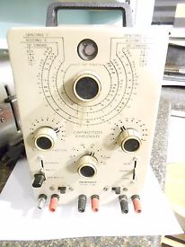
IT-28 Capacitor Checker
Heathkit 1969 - Catalog 810/69
Prices
Kit IT-28............................$31.95
As of 12/9/2017:
Manualman.com replacement manual.....$17.00+ S/H = $21.42
Introduced in the 1969 catalog sometime in mid to late 1968, the IT-28 was a new generation of equipment that was starting to come out of the Heath research department. It featured what some called the "New Look" brown and tan color scheme with differently shaped knobs. Unlike it's IT-11 predecessor, the IT-28 kit builder was given the option to wire it for 240VAC for use in Europe. It featured a grounded three-wire power cord and a spring-clamp on the 6AX4 rectifier tube socket to keep it in place during handling and transport. Unlike the IT-11, which used adjustable set-screw knobs, the IT-28 used the less desirable push-on knobs that can’t be easily re-adjusted or replaced should the plastic crack where it is formed to fit the metal insert holding the knob onto the "D" shaft. While it's older sibling, the IT-11 was introduced in 1961, this one picked up and ran with it from 1969 until 1977.
Of the functions the IT-28 has, probably the most useful is the DC block or leakage test of capacitors. This feature can be measured with a VTVM and, if you know how to use it that way, will be a little more accurate. This tester offers a graphical representation of the condition of a capacitor giving you a little better than "ballpark" idea of the capacitor's ability to function. Capacitance meters tell you capacitance and maybe ESR. A bad capacitor can still look good on a meter like that but give you nothing to go by in terms of rated voltage or current leakage. So many will use the old wax type capacitors like Bumble Bee's, Yellow Jackets, Black Beauties, electrolytic types and such thinking they are still okay to use. Some are paper-in-oil, regular paper, some with electrolyte solution, others with Mica or some kind of dielectric. Many simply go bad on the shelf or through use. You can't stop it. But you can stop burning out an expensive rectifier tube or pricey transformer by knowing more about the capacitors you want to use in a new project or restoration.
The IT-28 will test capacitors at different voltages based on the voltage rating of the capacitor being tested up to the maximum or 600V. Capacitors rated at higher than 600V will give skewed results due to the lower voltage supplied. To give you an idea at what point the capacitor's ability to do it's job, voltages are only one facet of this. The switch below the Range Selector on the left of the panel is labeled in three positions:
Electrolytic
Min. 'lytic
Paper, Mica, Etc.
Paper, Mica, Etc. mode measures leakage from zero to 2 microamperes.
Min.'lytic mode measures leakage up to 15 microamperes.
Electrolytic mode measures leakage up to 2 milliamperes.
Note: all three modes are initially set with the Leakage lever set to Discharge. Then switched to Bridge for the current leakage test.
For example: To test a paper capacitor, set the Leakage lever to Discharge. Set the capacitor type lever to Paper, Mica, Etc. Clamp the leads for your paper capacitor in the Test posts. Set the voltage selector to the closest voltage of the capacitor's rating without exceeding it. Set the Leakage lever to Bridge. If the eye won't open it is leaking at 2 microamperes or more of DC current.
Switch the right-hand lever down to Leakage. If the eye opens, it has charged. If not, move the lever to Discharge and select a lower voltage. Repeat until until the eye opens. At this point you will know better at what voltage the capacitor will function at without risking your project and turning that all important transformer into a charcoal briquette.
The above example does not take into account the Power Factor adjustment. This adjustment is mainly for Electrolytic capacitors that have an ESR value other types typically don't have. This adjustment counters the ESR of these capacitors to offer a more accurate reading and needs to be factored into the testing procedure. The manual will have these and other test procedures in detail.
_____________________________
June 11th, 2017
The popularity of the IT-11 color scheme makes them more collectible and thus more expensive to attain. Seeing this one in pretty good shape, physically, I decided to bid on it. When it arrives I'll do a visual check to see if any major issues need to be addressed. If nothing is missing or damaged beyond repair, this will become a partial restoration project. If more is required, it will be most likely turned into what I call a Re-Kit. My use of the term Re-Kit describes an assembled kit that is disassembled into it's discreet components again. New parts are used in the reassembled product.Until next time!
73!
_____________________________________________
Restoration Parts List
| Digi-Key Part Number | Quantity | Description | Customer Reference | Manufacturer | Manufacturer Part Number |
| 1135-1419-ND | 1 | RES 100K OHM 1/2W 2% AXIAL | IT28;? | VISHAY DALE [MIL] | RL20S104GB14 |
| 493-14448-ND | 4 | CAP ALUM 47UF 20% 400V AXIAL | IT28;C1;C2 | NICHICON | TVX2G470MCD |
| 338-3456-ND | 1 | CAP FILM 0.1UF 5% 400VDC RADIAL | IT28;C11 | CORNELL DUBILIER ELECTRONICS (CDE) | 715P10454LD3 |
| P12077-ND | 1 | CAP FILM 0.051UF 3% 400VDC RAD | IT28;C3 | PANASONIC ELECTRONIC COMPONENTS | ECW-F4513HL |
| P12250-ND | 1 | CAP FILM 0.51UF 3% 630VDC RADIAL | IT28;C4 | PANASONIC ELECTRONIC COMPONENTS | ECW-F6514HL |
| 338-3236-ND | 1 | CAP FILM 0.022UF 5% 630VDC AXIAL | IT28;C8 | CORNELL DUBILIER ELECTRONICS (CDE) | 150223J630DB |
| CMF1.00MHGCT-ND | 1 | RES 1.00M OHM 1/2W 1% AXIAL | IT28;R12 | VISHAY DALE (VA) | CMF551M0000FKEB |
| 1135-1417-ND | 1 | RES 1K OHM 1/2W 2% AXIAL | IT28;R16 | VISHAY DALE [MIL] | RL20S102GB14 |
| 1135-1437-ND | 1 | RES 820 OHM 1/2W 2% AXIAL | IT28;R17 | VISHAY DALE [MIL] | RL20S821GB14 |
| 1135-1425-ND | 1 | RES 2.2K OHM 1/2W 2% AXIAL | IT28;R19 | VISHAY DALE [MIL] | RL20S222GB14 |
| PPC47KW-2CT-ND | 4 | RES 47K OHM 2W 5% AXIAL | IT28;R1-R4 | VISHAY BC COMPONENTS (VA) | PR02000204702JR500 |
| CMF4.70KHGCT-ND | 1 | RES 4.70K OHM 1/2W 1% AXIAL | IT28;R20 | VISHAY DALE (VA) | CMF554K7000FKEB |
| 1135-1418-ND | 10 | RES 10K OHM 1/2W 2% AXIAL | IT28;R21-R29 | VISHAY DALE [MIL] | RL20S103GB14 |
| PPC22KW-2CT-ND | 1 | RES 22K OHM 2W 5% AXIAL | IT28;R32 | VISHAY BC COMPONENTS (VA) | PR02000202202JR500 |
| 1135-1431-ND | 4 | RES 47K OHM 1/2W 2% AXIAL | IT28;R35;R37-R39 | VISHAY DALE [MIL] | RL20S473GB14 |
| PPC33KW-2CT-ND | 1 | RES 33K OHM 2W 5% AXIAL | IT28;R5 | VISHAY BC COMPONENTS (VA) | PR02000203302JR500 |
| CMF1.50MHFCT-ND | 2 | RES 1.50M OHM 1/2W 1% AXIAL | IT28;R6;R? | VISHAY DALE (VA) | CMF551M5000FHEB |
| 1135-1416-ND | 4 | RES 100 OHM 1/2W 2% AXIAL | IT28;R7;R11;R41;R42 | VISHAY DALE [MIL] | RL20S101GB14 |
| 1135-1426-ND | 2 | RES 220K OHM 1/2W 2% AXIAL | IT28;R8;R10 | VISHAY DALE [MIL] | RL20S224GB14 |
| 1135-1433-ND | 2 | RES 560 OHM 1/2W 2% AXIAL | IT28;R9;R15 | VISHAY DALE [MIL] | RL20S561GB14 |
| 1135-1435-ND | 2 | RES 680 OHM 1/2W 2% AXIAL | IT28;R9;R36 | VISHAY DALE [MIL] | RL20S681GB14 |
___________________________
June 29, 2017
I received the IT-28 last night and opened up the box. My first view of this vintage piece of test equipment history was a sight to behold. Though it is in a little bit more of a rough shape than I thought, it looks to be complete and will be put on the restoration list.Below are the pics I took. I did remove the cabinet to set the Eye tube back into its clip for the assembled views.

 |
| Old electrolytic capacitors on the left, a fuzzy transformer on the right and lots of carbon composition resistors. This will be totally gutted and rebuilt with new. |
 |
| You can see the Eye tube was dislodged from its clip during shipping. Besides the odor, the tube in the foreground has the telltale smoker's dust bunny on the "top" of the tube (when the cabinet is sitting upright). The static attracts the dust and the tar and nicotine collect on it causing more dust to stick. Over time the tube can overheat because the bunnies act as insulation and the tube cannot dissipate the heat like it should. Similar in principle to the halogen headlamp bulb where the oils from your fingers create hot spots on the very glass trying to dissipate the heat. |
 |
| Notice the marks of where the ID tag was located. The serial number cannot be determined but this is only an operational restoration. |
All four feet are attached but sometime during its previous life, was dropped and dented the bottom of the case. It rocks a little bit but can be dealt with. The paint on the faceplate is in good shape and will look much better when all the tar, nicotine, and smoke coloring is removed. This was used in a heavily smoked-in environment which was not disclosed by the seller. Since the seller acquired this through an estate sale, he didn't even know what this was or what it does so I'm not going to complain. I will repaint the cabinet anyway but will not duplicate the crinkle texture as this is an operational restoration, not a concourse one.
Inside I found a few brown fuzz balls attached to the tubes and transformers. Due to the high amount of contamination, the checker will be completely disassembled. The cabinet and faceplate will be washed with Ivory soap so there won't be any solvents to attack the lettering. If that doesn't work I will have to try a little bit of Super Clean or Simple Green on the cabinet just to see how they work. I'm willing to sacrifice the paint on the cabinet to try a few things to help with future projects. I haven't settled on a color or a finish. Gloss, semi-gloss, or flat? I was thinking of a flat desert tan that might be a tad darker than the face. I don't think I'll choose this light brown again or the signature gray or even black. They just won't look right with the tan faceplate. If anything, I'll choose a much darker brown if I go that route.
After I put it back together from its inspection, I washed my hands of the residue and will be using surgical gloves when handling this item in the future until I can get it clean enough to handle bare handed again.
73!
_________________________________
July 30, 2017
As I was building the BOM on Digikey for my IM-13, I decided to check the resistors in the capacitor tester as well. Sure enough, they too were waaaaaaay out of spec. So I decided to combine the two orders to save on shipping as a single project order. Unfortunately I forgot to get the parts for the TC-2 so I could test the tubes for my projects. Chicken? Egg? I dunno which should be first. I need the meter to test the checkers and need the tube checker to test the tubes in the meter and the cap checker and need the cap checker to decide if I need to replace capacitors in all three. <sigh>So after considerable time researching the three 2% tolerance capacitors, I finally found, I hope, suitable replacements. Their values and materials used to make them are the same but the construction is different. I wound up having to buy PC mount brick capacitors to get the exact same specification caps. I did buy some Mica's that were the same value but I haven't been able to find whether or not they can be used in place of the old Mylar® (polystyrene) caps. I've heard it both ways. You can replace one for the other from both camps. Well? That doesn't help when nobody says why you can or can't. So I'll have the Mica's as a fallback.
The unit is still filthy. I bought two cans of CRC QD Electronic Cleaner and will spray the heck out of this thing to clean it up. The faceplate will be removed from the assembly so as not to damage the graphics. That'll be done with warm, soapy water.
The cleaner will wash the smoke, tar and nicotine off everything so when I go to desolder connections I'm not having to breathe the mess. I might have to desolder the transformers first. Getting any cleaner down inside either could spell disaster if the enamel is dissolved. If I don't, I might find the "charcoal briquette" Mr. Carlson's Lab sometimes mentions.
73!
_______________________________
November 19, 2017
 |
| And so begins another restore-to-ops project. |
With the transformers removed I can spend some time getting the know the insides of this unit and whether or not to just chuck it in the dish washer to get the remaining residue off of everything. All of the rotary contacts are blackened so there's the silver and copper spoilage issue there. Each of these will probably need some manual labor to scrub them clean. I tried DeoxIt and they're still black so the Dremel will be called upon with a fresh stainless wire wheel to clean things up. Other items noted are the wiring and solder connections. These are in very good shape and it's too bad I have to take apart so much to be able to clean the rotary switch contacts. But, it will benefit the device in the end. All of the wiring is solid-core with the exception of the transformer leads.
The switches that are enclosed in 'cans' will need to be disassembled and cleaned as well. I harbor no ill-will to the previous owner but cleaning up items in smoked in environments aren't any fun. The main shafts of the switches and variables will also be cleaned and lubed with Labelle 106 PTFE grease as done in the IM-13 and TC-2.
I have the rest of the parts listed on DigiKey ready to purchase. If you are interested in the list, please check out this project's page at the top. Note that the precision resistors are not included in the list. Only the carbon composition resistors are. Also, I did include capacitors C1-C4, C8, and C11. These are 'must replace' items to be on the safe side. If you have a properly working IT-13 or IT-28, check these to see at what voltage they will fail to charge at. If they fail at any voltage below their rating or if they leak DC current higher than the capacitor type selector indicates should be good, it goes without saying that you must replace them. It is possible they can be used in lower voltage installations if they do pass the DC Leakeage test okay reliably at a lower voltage.
There are two ceramic capacitors on the Mains side of the transformer. These are most likely transient filters with very high values. I researched the X2/Y2 safety capacitor idea and will install two Class Y (Y2) safety caps. The Y2 configuration is designed for a line-to-ground connection but is also rated to work as a line-to-line filter. The X-Class filter capacitor is not rated for line-to-ground use. Both types are rated as high as the AC mains feeding into them. 120VAC mainly in North America and 240VAC in most other countries. It could be stated that these types of capacitors are your first line of defense.
Here's a pretty good explanation of their use. http://powerblog.vicorpower.com/2013/06/what-are-y-capacitors/
In two-wire power supplies where there is no ground terminal back to the outlet AND the two-pronged plug is NOT polarized, you could conceivably have a 50% chance of making you chassis HOT instead of Neutral. That's depending on how the power supply is wired and how the potential difference between HOT and Neutral relates to the chassis. Most transformer power supplies can utilize a safety ground on the mains side of this type. Please see the schematic below.

Safety capacitors should incorporated into all tube equipment. Safety First.
That's it for tonight. 73!
_____________________________________
December 9, 2017
Wow! Time sure does get away! I got a chance to do some more tear-down of the unit. It ain't purty, believe me! I am still, unable to locate a complete manual online. Most have only 14 of the 30 pages and none include the assembly section. Was fortunate enough to find a complete parts list and schematic.This unit requires a complete overhaul and some chassis straightening. An assembly manual would be awesome but I'll have to go to manualman.com for it. Corroded connections, cold solder joints, heavily tarnished contacts and of course, bad caps. All old news now. My hard parts have arrived and I'm ready for some construction but the clean up still remains. As with the TC-2 Project, I'm tearing it down to kit form to become a Re-Kit. 20AWG wire will need to be procured and I will return to the seller I purchased the TC-2's 18AWG 600V hookup wire kit from.


Having said that, I paused to order a manual from manualman.com so I wouldn't forget...again. I also have Dad's 23 channel Lafayette CB/WX radio. I don't remember the model number but manualman has a large section for Lafayette equipment so I'm sure they would have one. MANUALMAN and Lafayette Equipment Manuals from MANUALMAN

It's cold here and rainy. I'm going to warm my feet up over something that has the magic glow.
73!
____________________________________
December 22, 2017
I sat down at the computer this evening and put on some Christmas Music to pipe through the speakers. Having done that I swiveled around to the workbench and began the next phase of the restoration. Desoldering and cleaning of the individual parts. Namely the lever switches and the rotary switches. |
| About half of the components ready for cleaning and testing. |
 |
| The other half. |
With that in mind, I'll keep these parts in place and clean the switch around them. The contact material on the rotary switches is silver and has blackened over time. In most cases, this is okay as the oxide is metallic and conductive. Though one should be careful in what cleaning agents are used if the oxide is to be removed to prevent accelerating the oxide buildup.
In my case, I made sure the contact pinches the rotating trace to make a good contact. I found four contacts that lifted and did not make contact at all. A couple of others made contact but in only one position out of three possible. The gap was simply too wide. A gentle manipulation of the contact is needed to close the gap. I used a precision screwdriver against the bend next to the rivet and tapped the end of it with another light object. Hard to describe and harder to video. Here's an exaggerated drawing I hope will help.

That's it for tonight. I probably won't get any work done on it for a week or more but I will return as soon as I can.
Merry Christmas and Happy New Year!
__________________________________
January 10, 2018
Firing up the soldering iron I was determined to not let much get in the way of the project today. I knew I had a few things to do but I really wanted to get back to it. So I did. Though it's not much, I soldered the resistors to the voltage selector rotary.
 | |
| Note the one tiny brown Vishay-Dale about the 9 O'clock position. This one does not have a banded value. Instead it uses the actual values in easy to read print. This one was the only 4.7K ohm resistor and the only one I could find from Vishay-x of that value in metal film at the time. Oh well. I ain't doing this for cosmetic points. ;-) |
The resistors used are in the parts list at the beginning of this page. All are Vishay-Dale or Vishay-BC. About half are Milspec and the other aren't but all are metal film in 1% or 2% tolerances with the exception of the 2 watt which is 5%. There are no metal oxide or carbon composition parts. Similarly, the capacitors are Cornell-Dublier or Panasonic on this project.
The arrangement of the resistors are straight lines toward the center instead of the usual, canted angle you see in 99.9% of all the others out there. I know why they are canted over but I wanted to build this according the diagrams in the book and the diagram shows them to be angled straight in toward the center. The diagram also shows them to be evenly spaced and not overlapping. That might work with 1/4 watt resistors but not these 1/2 watt ones. So I staggered them up, down, up, down and so on. Funny how the 2 watt 22K is actually smaller than the others. Still a metal film with a different manufacturing method.
The next step was to install the tube sockets. Now these sockets are Phenolic wafer types. They are constructed with the bottom layer Phenolic board, then the pin sockets and the top Phenolic board to sandwich and hold the pins in place with rivets or collets at the chassis screw mount holes. Cheesy. But that was an inexpensive way to put together a kit as tubes were seeing less and less market share by this time. So I am looking for some B9A 9 pin miniature ceramic chassis mount tube sockets. Antique Radio Supply here in the States have them in stock so I won't have to wait three weeks for the same thing in China even if I save a couple dollars through China. I'll pay the $4 shipping to get them here sooner from inside the country rather than wait for customs to get around to it before it leaves on the boat, plane or whatever. I hope Elon Musk is considering a 2 Hour Shipping service with his 35-minute-to-anywhere-in-the-world passenger rocket service. I'd pay five bucks more for that! Seriously though, if it costs us about $40-$60 for next day service with airplanes, I can imagine the medical field easily paying ten times that for medical transport of transplant organs around the world to the cities with his Falcon passenger service facility.
The other tube used in the IT-28 has an Octal base. It is also a Phenolic wafer type socket so I will replace that too with a conventional chassis mount. This socket is also stocked at Antique Radio Supply.
The last tube in the project is the "Magic Eye" tube, the 6E5. This is a 6 pin or UX6 or U6A type socket. It's common name is UX6 and its standardized designation is U6A and is common in tube checkers and testers. The socket is in good shape and cleaned up well so it will not be replaced.
Ahead in my next post, the pre-made wire harness. This is 20AWG wire and isn't in very good shape. I don't like the old plastic insulation nor the small gauge so I will upgrade it to the 18AWG 600 volt wire I used in the TC-2 Tube Checker. The harness won't be a harness as such due to the larger wire and insulation diameter but I will zip-tie it to keep it tamed. Half of the harness uses the basic colors and I'll start with those. The other half of the bundle use a white base with colored traces (White/Orange; White/Green, etc). I don't have any traced wire so I will need to be vigilant in labeling each one of these for proper identification.
That's it for tonight! I hope everyone had a great holiday season and looking forward to a better 2018.
73!
_______________________________
January 16, 2018
Had some time to begin the assembly of some of the chassis mounted parts. Namely, the range selector, balance adjustment, some terminal strips, fuse holder and the bridge transformer.

Now some of the components were previously not disassembled since they might be damaged or otherwise not required to be disassembled like the range selector switch and components.
I cleaned up the transformer with the wire wheel on the Dremel then wiped it down with a damp cloth of rubbing alcohol. It took an especially long time to get the enamel off the bottom of the mounts so the core's bracket would make a good connection to the chassis. Likewise, all of the terminal strips were wire-wheeled and rubbed down with electronic cleaner from CRC. The insides of the balance adjustment were in good shape and showed no corrosion or jumpiness when turned using the oscilloscope to measure noise in the pot. The rotary switch, acting as the range selector showed no problems either. I'm still looking for specs on the bridge transformer but there are no shorts between the primary, secondary and core.
I have reached the point where the harness is to be wired in. I haven't started it yet as it is late and will be quite involved. I don't especially like stopping in the middle of such an operation. So I will update with the harness wiring next time.
This completes my update for this round.
73!
__________________________________
January 19, 2018
Happy Birthday Dad! Just wanted to get that in there as I owe a lot of my interest in electronics and radio to him.I'm trying out this font color. I noticed when proof-reading the page the white seems a bit intense. I use this font color on the Shack Happenings page. Please let me know what you think. Thx!
I have been sick for the last few days with flu on top of a sinus infection. Ugh! I felt well enough this afternoon to get up and try to do something productive. So the workbench was the first place I came to. That was about 8 hours ago and I'm happy to report much progress has been made. I'll let the photos tell some of the story.
 |
| Received the new ceramic sockets with one caveat. The 9 pin miniature is rotated 90 degrees from the original. This means the wiring lengths may change a little. |
 |
| The original Octal socket didn't have a retaining ring so the tube clamp or catch just screwed to the chassis. The ceramic Octal does. At the time I was planning to mount the socket on the tube-side of the chassis. So I used a nibbler to cut a small amount of the flange to clear the retaining ring. Well, I figured later there was a reason the original socket was mounted on the other side of the chassis so I did the same and didn't need to remove anything. If I do change my mind later, it's already taken care of. |


 | |
| The B9A socket (9 pin miniature) needed a 7/8's inch hole and had to use a step-bit to drill it out to the correct size. A little sanding drum on the Dremel made quick work to clean up the burrs. By this point in the wiring, fully half of the wires are NOT soldered! |
The resistors on the B9A socket are 1/2 watt rated except the little one without any bands. That one is a 1 watt. These are made by Vishay-Dale and are Mil-spec. Strange these are larger than the 2 watt versions by BC. But the datasheets match the specs of the parts so I won't worry.
 |
| One of the original binding posts. It's hard to see but the mounting bases have four pegs molded in them. |
 |
| Coupled with the 'flat' on the post itself to match the molding in the base, the pegs lock them in place to prevent rotation. This is no longer the practice as now the holes are stamped round with a 'flat' spot. If I cannot locate any original binding posts I'll have to put the nibbler to work again. |
 |
| Finally reached the steps to mount panel parts and mate the chassis to the front panel, sans binding posts! What you see here...the fuse holder and bridge transformer. |
 |
| Not quite finished. Still a ways to go but shaping up nicely. |
 | |
| On this side sits an RCA 6E5 cathode ray indicator or "Magic Eye" tube. RCA trademarked the catchy name in the mid 1930's. Other names used are: cat's eye, tuning eye and idiot lamp. |
At this time there are fewer unsoldered connections than soldered ones but not by much. The 6E5 had to have a little extra slack in the wires to get it to sit level as in the photo above. The tube is pushed up against the front panel to help hold it centered in the view port. Odd that the tube was installed and plugged into it's socket early in the build. I think it had to do with the wiring and getting the socket clocked correctly so the tube wouldn't tend to rotate as the wires found their point of neutral tension. During this part I wrapped the tube in the small bubble wrap to protect it while handling the chassis. This tube's data code shows 7452. I can't tell if it's the 52nd week of 1974 or the 74th day of 1952. My other 6E5 has 2-43. It's definitely 1943 vintage but I don't know if the 2 represents February, or the 2nd day or 2nd week of that year. The date codes I'm familiar with use the week/year nomenclature from 70's and later technology like integrated circuits, storage drives, and the like.
That's it for today/tonight. Hope to get back to it in the morning sans binding posts.
73 and good night!
_____________________________
January 21, 2018
I didn't get much done today. Feeling better and better from the flu though. I installed the two sets of binding posts I have even though I only have three caps for them, two red and one black. Not sure where the second black one is. I thought I had one. The third set of binding posts are a total loss. These aluminum pieces were so badly galled that one snapped off in trying to work the cap off. The other wouldn't even budge. I kept the base pieces and tossed the metal. In order to wire up this pair I used a pair of 1 inch long 6-32 steel screws and nuts. This way I could at least wire them in on the solder lugs in the correct orientation. I have two modern binding posts but they will require drilling. I'm not ready to try that. I'll search a bit first for some that are the same size at least. If that doesn't pan out, well, I guess I could go a bit more modern. This device isn't as important to keep as original as practical like the VTVM and the tube checker but something closer to original does help maintain the look and character of the device.


The two posts for this position are for an external standard oscillator. Since I do not have an external source now, these will remain as screws. I can paint liquid electrical tape over these to cover them later. The two posts for the capacitor/resistor/inductor tests were the two most important terminations.
That will do it for this evening. 73 everyone!
_____________________________________
January 24, 2018
Ran into the issue with the old high voltage disc capacitors across the line-to-ground connection at the primary of the transformer. Not keen on using these. They were used as that is what was available for the purpose. Metal Oxide Varistors (MOVs) have been on the scene since probably the late 1930's to my knowledge and I believe they were first introduced as lightning protectors on telephone lines. I bought them from Radio Shack in 1979 or 1980 when I first saw them stocked. I used them to turn regular power strips into surge protectors by installing three of them.On Friday I will order some Y2 safety capacitors to use instead. I don't like jumping ahead the steps to continue with progress though. Seeing as I am working this weekend anyway, I won't make progress so it can wait. The next steps of the assembly after installing the safety capacitors involve the pre-assembled wiring harness which I did not re-use. So the easy part is done and I now have to pay very close attention to the connections as I build the harness in the cabinet while moving ahead through the assembly steps. I want to have time and be clear headed when I sit down the begin. The last thing I need is to watch it all go up in smoke during the insanity test.
73!
_____________________________________
February 6, 2018
Good evening. Got a little bit more done with the project tonight. I am more than half done with the wiring. This has been slow as I have had to wire everything with individual conductors as the old main harness wasn't usable. Heathkit provided the harness as a prefabricated sub-assembly in the kit. I'm using what I had on-hand from the TC-2 project which is 18AWG 600V stranded hookup wire. It's diameter makes this more difficult to work with especially in the tighter confines of this chassis while still trying to route the wires as the original harness would have. It isn't easy, believe me. Using this wire makes it twice as large to handle. Why do it then? Like I said, I used what I had on-hand to avoid the expense of 20AWG 300V solid core wire.Now going through the process does bring up something anyone can make mistakes with. Using the same color more than twice for two different parts of the unit. There are two gray wires and two violets. Buuuuut, they do have a common junction point so they don't count as separate circuits. There color-with-tracer wires as well. Fortunately there is only one color-with-tracer but without each of them in the prescribed location at the time of connection with a prefabricated harness, it is difficult. More so when the assembly steps have you connect one end AND tell you not to solder it then doesn't have you connect the other end until later. It can get a bit dicey. Now then, the assembly steps also have a kind of ambiguous nature too. For example, on page 14 the fourth steps states: "Connect a 5" wire to lug 3 of tube socket V1 (NS). Position this wire beside terminal strip F. The other end will be connected later." Okaaaaaay. So what color do you use? It didn't specify one so I can pick for myself. Knowing I would have to be able to identify it later, you really can't use a color already used, can you? Well yes you can. Since many of this type of wire was white in the original wiring in side, I just used white even thought White was used in the harness. Now I used a label maker using 1/4 inch wide labels. I used codes to identify the wire on both ends so I could recall where it was connected. In this case I uses V13 to signify socket V1, pin 3. The diameter of the wire allows just enough space in normal type on the label to see just the three characters. When a step called for a Red-White wire I cut a piece of Red wire and put an RW on the label. Not as a flag but wrapped it around the wire after trimming the label close to the code on one side. Beats the heck out of trying to write on it. Yeah, I tried that too. So I went back through the wiring sequence as if the manual instructed the builder to connect one end of such-and-such wire then connect the other end of such-and-such wire at the same time.
Now that I've caught up after jumping around the assembly steps for the most part, I have one more section that is (more or less) in sync with the steps left. There are a couple of items I've left for later with a double-check on whether it calls for soldering or not. There are a lot of (NS) in there and a careful inspection will be done to ensure all solder joints are in fact, soldered. I figure it's these situations where you don't solder something until later is the reason why many who've built kits miss a solder joint or two. Heathkit technicians found this and poor solder joints to be the two biggest problems the devices had back in the day. Twice I soldered a connection and had to desolder it because of another wire or component that came up later in the assembly. Just have to pay closer attention to the (NS) or (S-x) notation and you'll be less likely to miss a solder joint.
Currently I'm on page 17 and stopped after connecting the Orange-White wire to pin 3 of the Type switch (R). I did jump to page 19 to perform the first six steps to clean up other loose ended wires still requiring a place to connect. This helped in cleaning up the space. When all the wiring is done, I will add small wire ties (zip-ties, zap-straps, zip-cinches, etc.) to make the wiring a bit more organized and finished looking. By no means will this bundle of wires look like a harness. It's just too large to fit through some of the cut outs or grommets. In fact, I have just barely fit six of the wires through grommet H for the eye tube. I had to use a little silicone spray to get it to start because the fit was so close. Almost felt like just jamming a #1 Philips head screwdriver through the center just to enlarge the hole to get it go. Decided not to since damaging any wiring was a bad thing. ;-)
 |
| In one side... |
 |
| out the other. |
It's late (early) and I need to get to bed so I can enjoy my day off.
73!
___________________________________
February 8, 2018
Good evening! I spent a little time on the project and have completed 99% of the harness wiring. I have stopped on page 20 of the assembly manual at step 17. I count the steps per page from top to bottom, left to right column. The step I'll be performing is to "Connect a 4" wire from lug 8 of tube socket V2 to lug 6 of switch S." when I pick up the project next time.The wiring ain't purty but I believe it will work. Should this project fail, I'll put it aside and begin the next one. Repair on the IT-28 will be a complete rework with 20AWG 300V solid core wire and become another project. Perhaps the main reason it would fail to perform adequately would be capacitance between wires. The space between the conductors inside the insulation is greater and should thus be more immune to interference from parallel wires. There may be conditions that are created that can allow interference to happen the original wiring harness didn't induce due to the design. It was tweaked to work a specific way with a specific wiring method. Minor changes shouldn't have a great affect on the unit. However what looks good on paper doesn't always act so in reality.


No doubt the 18AWG wiring is fat. I have to be careful in that undue tension is not put on the solder lugs of the rotary switches lest they fatigue and break off.
I have thought about the two large electrolytic capacitors in series and thought about balancing resistors across them. Not sure why Heathkit didn't incorporate this but it is possible it would matter to the circuit's accuracy any more or less than negating the added expense of two more parts. I calculated 270K ohm values at 1/2 watt across each capacitor but may put in 300K at 1 watt. Still debating to do this mod or not. The design worked for many years without them so I hesitate doing it now. I may do some testing without them then install them and see if there is any real performance difference.
73 for now!
__________________________________
February 11, 2018
Reached a major milestone today. The wiring is complete. I've gone through the unit to ensure all the solder joints are really soldered and there are no loose ends floating about. I checked the 6BN8 and 6AX4GBT on the restored TC-2 and they checked out good. Or as good as an emission tester can. ;-)A couple of things left to do. Acquire a 1/2 amp slow blow fuse. Since 125V versions are no longer available, I will have to settle for the 250V currently made. Even at that, I'm finding them at $3/ea with a minimum purchase of 5. Will be looking some more. I found that Digikey has 3/16 amp fuses but would be waiting for the 1/2 amp slow blow for nine weeks and wind up paying over $5/ea. If I find another slow blow in any of my equipment, I'll borrow it to do the calibration procedure.


That's it for now!
73!
________________________________
February 14, 2018
The fuses are on the way!
I hope to have them by Saturday so I can use part of the weekend testing the unit and calibrating it. Slow blow fuses aren't cheap by any means so it was a shock to find out how expensive they can get. The .31mA fast fuses I got for another piece of equipment were $4.21ea. Glad I don't need more than one with a spare. This unit needs a 500mA slow blow fuse so for less than the other two, I got five on the way.73 for now!
_______________________________
February 20, 2018
Good evening all! Just a short update: My fuses came in today and was ready to start calibrating the unit. However, I seemed to have forgotten to order the spring inserts for the knobs so they won't fall off or have sloppiness in the movement. I have contacted the supplier/manufacturer, Lectra-Products about the "D" spring versus the flat spring Heathkit used in the knobs. I'm for the D spring if they fit the cavity in the knob properly. Once I get that information, I'll order and wait for them before the final calibration. The main piece is to calibrate the frequency pointer to the scale. But I can perform an initial set up tomorrow (21st) to perform the sanity test and smoke test. Passing this hurdle will allow me to complete the calibration and the project.73 and have a good evening!
________________________________
February 21, 2018
I apologize for the grainy video. I didn't have enough light apparently.
It passed the smoke test but that's as far as it got. According to the test and calibration procedures the eye is supposed to be closed in all tests except the balance control in the extreme clockwise position.
Control Position
Bridge-Leakage Bridge
Gen. Int.
Type switch Any
Voltage 3
Power Factor 0
Range *
* For positions R X1 through C X1, the eye
tube should be closed with the balance control
in any position except maximum clockwise.
The instructions go on to say the tube should be open in the maximum clockwise position, yada yada. The tube never closed in any of the positions so I turned it off, unplugged it and took daughter to meet wife for dinner and declare it a fail.
I will take a fresh look at the wiring and check each connection and solder point again as the manual suggests later. Common sense really when you think about it. If the wiring pans out, I might see if I can check the 6E5 eye tube on the TC2 but seeing that it lit up from turning on the unit then got brighter when the Leakage switch was put into Bridge mode says it is working. Weak, maybe but working. So I must have miswired something or an original component is out of spec. I'll work from the 6E5 on back through the circuit to troubleshoot. Time to start cleaning up the workbench of this project's material and prepare for the next one.
73!
_____________________________
February 28, 2018
Spent a couple of short evenings troubleshooting the problem and discovered some voltages are way off. Thinking I would start at the 6E5 and work backwards through the circuit didn't reveal anything special except voltage issues.At the output of the power transformer the voltage read at 500VAC. I figure this is due to the mains power is 125VAC RMS these days instead of the 110VAC or 115VAC RMS back in 1971. So I accepted this variance to be normal. The next test was at the output of the 6AX4 rectifier tube. This tested at 201 volts. The schematic shows it should be 200VDC. So that is good.
The next test point down the line was pin 7 of the 6BN8. This tube is a Mullard IEC TwinDiode-Triode in a 9 pin miniature (Noval base) package having two rectifier sections and a section with grid. and pin 7 is the plate for section A. The voltage reading here is supposed to be 58VDC. The meter read 43VDC. Hmmm. That's not normal or seems to be in spec. On to the next test point.
Pin 6, section B plate voltage is to be -.4VDC but read 0. The same reading for pins 8, 9, and 1. On to the 6E5. Pin 2 is supposed to show 22VDC but the meter read less than 1 volt. This explains why the eye tube won't close it's eye at any point during the test and calibration. No driving voltage.
As expected I tested pin 3 and it showed 0 volts when it should be -.8VDC on the grid of the 6E5.
So I'm down to testing the tubes performance again. Since the 6E5 isn't getting what it should I can surmise the 6BN8 really is the culprit as all voltages from it are nowhere near what they should be. My next test will be with another 6BN8 if I can find it. It may not be in my box of vintage tubes and will probably have to purchase one online. Still not giving up.
73!
_________________________________
March 17, 2018
I bought a NOS NIB RCA 6BN8 tube to replace the 6BN8 the unit came with. Same result. So I'm now in the process of understanding why the wrong voltages at the test points are happening. I even tried the NOS 6E5 tube I purchased that is dated 1942 with the same results. It's brighter than the 6E5 that came with the tester but still nothing. I found that one of the capacitors connected to the 6E5 is 685nF instead of 500nf (.05uF). That might cause some issues so I'm going through my other HV capacitors with the 500nF value and using my LCR meter to see what value they are at. Just doesn't seem that 185nF can make such a difference but it's possible.Meanwhile, I am clearing off some of the workbench and getting ready to go into the IG-102 next. I haven't cracked it open since the first time after purchasing it last April at RARSfest.
That's it for tonight. Sorry for the shortest update yet. More will be posted once I find the problem.
73!
______________________________
October 29, 2019
It's not dead, Jim.
Good evening fellow Hammers. After beating my head against an elusive voltage anomaly in my Heathkit Capacitor Checker model IT-28, I have finally made progress. I no longer have a headache. That is all.
Okay. I made more progress than that. I got it to respond properly to the test and calibration procedures in the manual. I decided to trace only the positive 56 volts on the 6E5's grid, pin 3, backwards through the system. I should have done this months ago but frustration and a deadline for other items were a higher priority.
Okay. I made more progress than that. I got it to respond properly to the test and calibration procedures in the manual. I decided to trace only the positive 56 volts on the 6E5's grid, pin 3, backwards through the system. I should have done this months ago but frustration and a deadline for other items were a higher priority.
The grid should have been at -.8 volts. I began by removing the tubes out and checked the resistors associated with the connections to the 6E5 Magic Eye Tube. ( http://magiceyetubes.com/ ) One resistor showed an open circuit that was supposed to be 680K ohms ( Ω ) on pin 9 of the 6BN8. It looked to be soldered in and figured it was broken at the lead going into the body of the resistor. I de-soldered the connection to find it had not soldered properly. I had checked this before and it "looked" like a good solder joint. What I was seeing was the solder had made an umbrella over that point and hid the problem. I simply didn't put enough flux on the entire joint so the residue and oxidation settled over and on that resistor's lead preventing the solder to wick into the joint. It's by shear luck the lead didn't touch the solder terminal.
I was very happy to see this as this meant there was a chance this had been the problem since the rebuild!
A drop of liquid Kester 186 flux was put to the joint and ensured it had reached the resistor lead this time. It had and I applied fresh solder that wicked to the proper points throughout the solder terminal. Wow! I had more hope now than before. I was beginning to prepare my self to tear it back down to it's component parts and start all over before this discovery.
I put the tubes back in and checked calibration pots, AB, AC, and AD and found I had reversed a pair of wires for the calibration adjustment. It still would have worked but the calibration would have worked in reverse and until found, might have been maddening trying to figure it out. Glad I found it before I powered it up this time. Switching the offending wires, I was ready to power it up.
So with the variac, provided by my fellow crewmates in our Hamtastic Crew FB page, I brought the power level up until the eye glowed green at about 90 volts on the mains. Once it did I flipped the Current Limiter out of circuit and the voltage went to the house 124VAC on my meter and the eye tube came to life with an OPEN eye position for the first time!
The meter was removed from the AC line power and put across the chassis ground and pin 3 of the 6E5 eye tube in DC+ mode. The voltage stabilized at -.9 volts just a hair off of the -.8 volt on the schematic. I did the initial test in the manual and found the eye tube now responded to the first set of tests.
It's late and rather risk shortening this wondrous occasion with discovery of my own breakdown voltage, I will call it a night.
I'd like to throw out a thank you to Buddy of The Radio Shop channel on YouTube for piquing my interest again with this. I came across a video he did with a restore-to-operation of the same model capacitor checker.
Thanks to the Hamtastic Crew for the variac which, with the addition of the current limiter I built, made this safer to work on. Thanks you guys!
 |
| Eye open for the first time! |
73!
_________________________________
Happy Halloween! - 2019
Last night I had some fun with the checker and thought I would share a short video testing the original Minimite 2x20 uF, 150V Dry Electrolytic filter capacitor that came out of the checker.

One half seemed to charge up quickly but as the video showed, the second half of the cap took a long time to charge and I don't think it fully charged at 150V. So I can keep it and restuff it later if I want to have the original "look" of its original build. So far I'm happy with the result and have since tested several other capacitors.
I have a few ceramic tubular capacitors that tested good by this capacitor checker. However, Mr. Carlson's Lab of YouTube designed and built a very sensitive leakage detector. How many will these old capacitors pass that test? Few will. Check out this exclusive project on his Patreon channel. He did a video on the device and posted it to YT here.
Since this is a working piece, it's now a completed project.
That's all to report tonight. Have a happy and safe Halloween!
73!
___________________________
I have been restoring my own IT-28 and recently repainted the back cabinet. I used Krylon ColorMaster #53566 Satin - Leather Brown. It is a suitably close match for me. You might pickup a can and test it out for yourself. Good luck with the project.
ReplyDeleteScott
Thanks for the color advice. I've been debating as to what color I want to use. Nothing really goes well with the tan face plate so a rich brown color will bring out the contrast nicely. I'll check into the Leather Brown next time I'm at H.D.
DeleteGenerally, the Silvered Mica caps only come in smaller capacities. At least that was always my experiences but they were the best for precision specs. The mylar dipped were always the next best at a much better price point and in larger capacities.
DeleteHi, great article! Did you get any further in this? I have the exact same problem as your last post,voltages same as you.
DeleteSorry I haven't gotten back sooner. At this time I had other priorities that took me away from the project. I hope to get back to it in December before the year is out.
DeleteFixed! One resistor showed an open circuit that was supposed to be 680K ohms ( Ω ) on pin 9 of the 6BN8 to chassis ground. It looked to be soldered in at the terminal strip and figured it was broken at the lead going into the body of the resistor. I de-soldered the connection to find it had not soldered properly. I had checked this before and it "looked" like a good solder joint. What I was seeing was the solder had made an umbrella over that point from the oxidation and cooked flux from before hiding the problem. I simply didn't put enough RA flux on the entire joint so the residue and oxidation settled over and on that resistor's lead preventing the solder to wick into the joint. It's by shear luck the lead didn't touch the solder terminal.
DeleteHi, thanks for the article, I acquired one of this units last week and I'm planning on doing a restoration, so the process you describe here is going to be very useful, thanks for taking the time. I downloaded the available manual from the web, but it's incomplete. Is there a chance that you have the full version with the assembly instructions included? It would be much appreciated. All the best!.
ReplyDeleteThank you for the kind words. My apologies for not replying earlier. I had to purchase a manual from manualman.com at the time. Nobody had a full manual in digital format. The Heathkit owner's group on groups.io may be able to help since purchasing the manual in 2017. Somebody surely has a digital version by now.
Delete