Welcome to the Nixie Tube Clock Project!
Let the good times glow!
Jameco
Mouser (2N5550 transistors)
eBay (found KW155ID1 = 74141 Nixie tube driver chips)

While I wasn't quite ready to embark on this quest, I spent a few hours perusing the 'net to locate the parts I wanted to fill the PCB I purchased during the Summer this year (2017) with. Now I do have a ready-made BOM list from the designer of the clock and all of the documentation downloaded from his site including the schematic. Since having looked around for the parts I wanted I discovered the vintage parts I really wanted (TI, Signetics, National) were pretty darned expensive.
So I fell back to punt and go with what I could find as a comparison. Well, it turns out the parts aren't super cheap due to their age either through the parts kit the designer sells or from other sources. For instance, the 7441/74141 high voltage BCD Decoder Driver IC's for the Nixie tubes are now available as Russian NOS pieces with the model number K155ID1 or KM155ID1. This is acceptable period components since the former Soviet Union kept original Nixie tube production much longer than anyone else. Even their Vacuum Fluorescent Display production went well beyond others for typical applications like alpha numeric displays using individual tubes. They also made multi-character tubes as well while we, and most of the rest of the world, relegated the use of such arcane display technology to the niche market of handheld games, HiFi displays and other custom applications. Testers for these types of ICs can be bought or built to tell you if it is good or bad. Click here for some samples. Dieter has a page where he designed and built a tester that tested good or bad AND if it was a 7441 or 74141 or equivalent so you knew which type of chip it was for proper identification when there was none. Go here for more info.
Through the research I have found the more difficult parts from Jameco and eBay to fill out the BOM. Mouser too will come in handy with some components when the time is right. All this means extra shipping charges so the bulk of the expensive parts, being at Jameco, will be purchased from there first. I'm skeptical of the KW155ID1 chips on eBay and may look elsewhere for alternative versions of the 74141 or I may buy them from the designer (TES) in a 7441-5 kit.
To drive most Nixie tubes you'll will require about 170 volts. Not too much more than your typical North American outlet source. But the clock is designed to run from a 12VDC 1/2 amp regulated wall wart and that means a booster is needed. Enter the designer's solution to that little problem in the form of the 1364 HVPS.
As I add up the parts, I'm realizing the expense, before purchase of the tubes, is climbing rather rapidly. Oh well. I choose the hobby and I love it!
Until next update, 73!
________________________________
Other stuff like resistors and capacitors will come from Digikey as I have more parts I need from them for other projects. I like Digikey because I can usually get Vishay-Dale resistors. Where I need carbon composition types, I usually go to Mouser. Surplus Sales of Nebraska is a third choice for other things like knobs and #47 pilot lamp holders.
________________________________
I received the GPS module I'll experiment with on the second clock of this project as the time base instead of the line-sync method on this one. The first will be built as designed and left alone while the second becomes a test-bed of sorts.
The GPS module can be found here. It's purpose was for use on a quadcopter to give it its location information. I'll use the PPS pin to inject that signal into the clock. So far it looks good on paper and really no mods are needed. Simply switching out the clock pulse from the original time base final stage and inserting the PPS should work and offer higher accuracy than the AC grid.
Hoping to see the IN-12A's and extra KM155ID1's by the end of the month. Should have the IT-28 completed and start building the first clock by then.
73!
_________________________________
73!
_________________________________
I finally received my IN-12A Nixie display tubes! I checked the dates on them just to see what they were. They range from 1975 to 1984. They all have OTK and a number on them in addition to a number inside a diamond. Not sure why this seems to be a big deal with collectors/makers but the stamp is there. I guess OTK Interesting note though. At some point in their production the top ceramic donut insulator for the top and bottom supports that secure the grid went from white to a faded violet. The earliest example I have with the violet insulators is 1978.
The only thing left from Christmas I'm waiting on are the KM155ID1 (74141) high voltage Russian Nixie tube driver ICs. Those should be along any time now.
That's it for tonight. Next order I place for this project will garner all of the components needed to get started.
73!
_________________________________

These are USSR vintage KM155ID1 driver chips. Date codes show 10 of the twelve ICs manufactured during the second week of 1990 (9002) and two a hair over a year later during week 5 of 1991. They are of a ceramic construction as I hoped they would be. Now I'll go back to Dieter's page and build a tester for them and other 7441/74141 driver chips using his project build information for some ideas of my own. I do not plan on using an ATMEGA chip so software isn't a requirement. I may just build a clocked circuit from the timing stage of my Nixie clock project as a standalone chip checker instead of a diagnostic chip type identifier and pass/fail tester like Dieter built.
That's it for now. Many other components are still needed before soldering can begin. Be sure to check back for updates.
73!
________________________________
The GPS module works but is terribly slow at acquisition and lock of signals. I have seen where it has taken a few hours to get a lock and produce the timed pulse so I'm not sure if this would be the best timebase unless it were to have it's own battery backup. There is a capacitor that looks like a button cell from a hearing aid but it is a capacitor. I might be able to adapt a battery with charging circuit or put in a diode to prevent charging of a battery. Not sure how I will approach this. I will consider another GPS module as well.
73 for now!
_________________________________
I haven't decided on a "case" or stand or platform or whatever you want to call it but it should be workable just fine without them. Just don't get too close and keep one hand in the pocket. Even thought the high voltage isn't from the Mains, it can still bite pretty hard on the output of the voltage booster. I may not even bother with the power plug and socket. I think I already have a wall pack that can do the job and just solder the leads to the board.
73!
______________________________
Now that the IG-102 signal generator is done, it's time to get on the Nixie Tube clock(s). I have parts for one complete clock, minus the cabinet, but will build the LS version first. The other version will use the original available parts, save for the Russian 74141 Decoder Drivers. Every chip will be socketed for easy repair however, I did forget to purchase the 16 pin DIP sockets for the 74141's. Those are on order now.
The first order of the business end of the project is to plan which parts to install first. Well, that's easy! How about the surface mount stuff you can't solder in, ay? Why not?! I learned a little trick from another electronics geek that works better than trying to apply solder to the pads first then set the SMC in place and try to hold it there with tweezers/jewelers pick while melting the solder. A drop of liquid flux, place the part, hold it down with said tool, apply solder to a clean hot tip and touch it to the end of the part. The solder will flow right to the conductive part of the component. Do it again for the other end of the SMC and viola! A mounted Surface Mount Component. I recommend the jewelers pick as the point will do a better job of holding down the part than a jewelers screwdriver. That way you won't twist the screw driver and dislodge the part. Works everytime.
I did 16 capacitors before calling it quits. My eyes are straining and my hands aren't steady from fatigue but before I go, here's a couple of pics of the work started. Good night and 73!
________________________
First was to plan the component installation. I usually start with the the smallest parts and work up in size since there are times when placement of a smaller part is made more difficult.

So I finished installing all the parts on the back of the PCB then flipped it over.
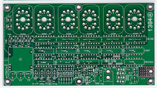
As for the decoder/driver IC's, I have the Russian made 74141 (KW155ID1). The 74141 added a blanking feature if the bit value exceeded 9. Remember, in binary, Zero is the first number and counts as one placement thus all bits set to 0000 in binary yields a Zero in the display tube. So any bit combination from 10 through 16 will turn off the output of that chip. Since this clock does not incorporate that feature, it seems pointless to use the IC. Ah! Except that the 7441 is much more difficult to find. They are pin-for-pin compatible and operationally identical for the first ten digits.
There is one IC per display tube except for the 10's position in the Hour display. Since this clock is a 12 hour clock only two numbers are used, 0 and 1 for the time. Two transistors are used to switch between them and the other two transistors are used to light up the AM or PM neon bulb.
That's it for tonight!
73!
_____________________________

The Cathode leads were bent around and down as these rectifiers are mounted on the Anode end. I cut and slipped on a piece of heat shrink tubing for each to guard against any short circuits. The soldering of the Cathode shrunk the tubing a little but it was cut to length so shouldn't shift.
The next few parts installed were the 16 pin DIP sockets for the 7441 high voltage driver IC's, a modified 8 pin DIP socket for the bridge rectifier, a voltage selector header, and the PM/AM neon bulbs indicators.
For the bridge, I pushed four of the pins out so I could solder the socket to the board and not have any shorting points. I was having trouble locating the appropriate socket so improvised the solution. The socket doesn't extend beyond the edge of PCB so keeps a clean look.

Next were the five 16 pin DIP sockets (no photo). These went in easily and were quick to solder.
The voltage jumper header was next to be soldered in. I already had a dual row .100" spaced breakaway header so I used three header pins with the spacer. After soldering, the tails were quite long so were trimmed off the bottom. A standard jumper block from my PC parts kit was installed on pins 1-2 for 5V operation. I don't have any notes as to why there's this jumper but with all of the TTL IC's on the board, don't think 9 volts is needed. I have yet to hear from the designer on any further information regarding this function. I mean, if it didn't run on 5 volts, why is there a 7805 regulator?
Also, there wasn't a specification on voltage supply other than 9VAC. Is there a range? Can I use 10VAC or 14VAC? and still function? The schematic did not show any other voltage value other than 9VAC. So it would be prudent to give the circuit what the schematic says.
Last are the PM/AM neon bulbs. Heat shrink tubing was cut to length for protection as these are powered with 170 volts as are the Nixie tubes. Safety first!

The bulbs are set to 3/4's the height of the display tube. Should I need to extend them for clarity if I decide to enclose this, I have more bulbs. I will most likely use heat shrink tubing to make a shroud if they don't seem bright enough.
The last thing I'm waiting on is the 9VAC 500mA linear power supply. This is a wall-mount type supply. Why linear? Because this is a Line Sync type clock that relies on the 60 cycle per second (60Hz) frequency of the AC line, the power supply must pass this frequency rate on to the shaper IC. This is the electronic version of what the induction motors were to the mechanically driven clocks that used line frequency to keep time. If a switching power supply were to be used and the switching frequency was all the counters saw, the the clock would be a counter, not a clock.
The process of turning 60cps to 1cps is done through a Line Clock Shaper (U14: 4121) to convert the sine wave into a square wave. Next the signal is run through a Divide by 6 IC (U6: 7492) whose output then is passed on to a Divide by 10 (U7: 7490) to achieve the 1cps clock rate.
Hopefully I will hear from him before the transformer arrives.
73!
_____________________________
As you can see in the video, the Nixie clock is running! The time was set to within one second of my "atomic" clock which sets every night upon the synchronizing signal. I think I've had a few power outages as my Line Sync clock on the Heathkit SB-610 fell behind by 45 seconds. My Grandmother wall clock is old-school wind up with pendulum and provided I keep it wound up, has been accurate to within a minute every few months.
This clock's time base comes from the 60Hz frequency of the AC mains in the house here in the States. There is no battery to keep a CMOS clock running should power drop out as there was no provision for a sub-clock within this clock. It uses decade counters and divider IC's to shape and ultimately provide the 1Hz pulse to increase the clock counter by 1 every second. This is a late 60's to early '70s example of Line Sync clocks.
I'll build the other clock to use a GPS 1PPS sync pulse to see if it's possible. It will have the same problem when the power drops out. I would need another clock kept in a memory and another circuit to allow it to reset the Nixie clock counters to Zero then pulse the hours/minutes/seconds counters to reset the time to the current time stored in memory. I'm not going to do that but I will test this clock on a standard UPS backup to see if the modified sine wave will cause problems. If it does, I'll need to get hold of a True Sine wave battery backup supply to prevent false triggering the counter.
So this clock worked on first power up after all. I'm quite pleased and look forward to building the second one. I'd like to make the display tubes sit upright to allow the main board sit flat. For that, I probably should learn KiCad or EaglePC software to build PCB foil patterns to make my own interface board.
Other projects await my attention so I bid this project complete. If I come up with a case, I'll post an update.
73!
________________________________

Dat's all folks!
73!
_______________________
Let the good times glow!
Parts Sources
TES - Taylor Electronic Services (Nixie Clock PCB and voltage booster)Jameco
| 74LS90N, DIP-14, ASYNCHRONOUS DECADE COUNTER | |||||
|---|---|---|---|---|---|
| 74LS92N, DIP-14, DIVIDE-BY-12 DECADE COUNTER | |||||
| 74LS00, DIP-14,QUAD 2-INPUT POS. NAND GATE | |||||
| 74121N, DIP-14,MONOSTABLE MULTIVIBRATOR | |||||
| 7417N, DIP-14,HEX BUFFER/DRIVER (O.C. HI-VOLT.) | |||||
| LM7805CT, TO-220/3, 5V 1A POSITIVE I-TEMP | |||||
| 1N751A, ZENAR DIODE, 5.1V, 500mA | |||||
| DF005M(DB101), DIODE BRIDGE,1A 50V SINGLE | |||||
| LAMP# A1A(NE-2),NEON, .48"L 65-120VAC, .500mA |
Mouser (2N5550 transistors)
eBay (found KW155ID1 = 74141 Nixie tube driver chips)


While I wasn't quite ready to embark on this quest, I spent a few hours perusing the 'net to locate the parts I wanted to fill the PCB I purchased during the Summer this year (2017) with. Now I do have a ready-made BOM list from the designer of the clock and all of the documentation downloaded from his site including the schematic. Since having looked around for the parts I wanted I discovered the vintage parts I really wanted (TI, Signetics, National) were pretty darned expensive.
So I fell back to punt and go with what I could find as a comparison. Well, it turns out the parts aren't super cheap due to their age either through the parts kit the designer sells or from other sources. For instance, the 7441/74141 high voltage BCD Decoder Driver IC's for the Nixie tubes are now available as Russian NOS pieces with the model number K155ID1 or KM155ID1. This is acceptable period components since the former Soviet Union kept original Nixie tube production much longer than anyone else. Even their Vacuum Fluorescent Display production went well beyond others for typical applications like alpha numeric displays using individual tubes. They also made multi-character tubes as well while we, and most of the rest of the world, relegated the use of such arcane display technology to the niche market of handheld games, HiFi displays and other custom applications. Testers for these types of ICs can be bought or built to tell you if it is good or bad. Click here for some samples. Dieter has a page where he designed and built a tester that tested good or bad AND if it was a 7441 or 74141 or equivalent so you knew which type of chip it was for proper identification when there was none. Go here for more info.
Through the research I have found the more difficult parts from Jameco and eBay to fill out the BOM. Mouser too will come in handy with some components when the time is right. All this means extra shipping charges so the bulk of the expensive parts, being at Jameco, will be purchased from there first. I'm skeptical of the KW155ID1 chips on eBay and may look elsewhere for alternative versions of the 74141 or I may buy them from the designer (TES) in a 7441-5 kit.
To drive most Nixie tubes you'll will require about 170 volts. Not too much more than your typical North American outlet source. But the clock is designed to run from a 12VDC 1/2 amp regulated wall wart and that means a booster is needed. Enter the designer's solution to that little problem in the form of the 1364 HVPS.
As I add up the parts, I'm realizing the expense, before purchase of the tubes, is climbing rather rapidly. Oh well. I choose the hobby and I love it!
Until next update, 73!
________________________________
November 27, 2017
Most of the IC's (listed at the top of this page) have been ordered from Jameco. The Russian KM155ID1 IC's are in, well, Russia. So I'll order the IN-12A Nixie Tubes from a supplier I've dealt with before on Wednesday or Thursday. I should them in about three to four weeks due to customs on both ends of the transaction but he has tubes cheaper than eBay so I can wait a little longer.Other stuff like resistors and capacitors will come from Digikey as I have more parts I need from them for other projects. I like Digikey because I can usually get Vishay-Dale resistors. Where I need carbon composition types, I usually go to Mouser. Surplus Sales of Nebraska is a third choice for other things like knobs and #47 pilot lamp holders.
________________________________
January 2, 2018
Good Evening and Happy New Year!I received the GPS module I'll experiment with on the second clock of this project as the time base instead of the line-sync method on this one. The first will be built as designed and left alone while the second becomes a test-bed of sorts.
The GPS module can be found here. It's purpose was for use on a quadcopter to give it its location information. I'll use the PPS pin to inject that signal into the clock. So far it looks good on paper and really no mods are needed. Simply switching out the clock pulse from the original time base final stage and inserting the PPS should work and offer higher accuracy than the AC grid.
Hoping to see the IN-12A's and extra KM155ID1's by the end of the month. Should have the IT-28 completed and start building the first clock by then.
73!
_________________________________
January 19, 2018
Just a quick update. I sort of tested the GPS module and saw that it does seem to get a lock. The LED on the board does blink rapidly as sentences are received from the various satellites. Only thing now is to connect it up to a USB-to-Serial adapter and make a interface for it to see what the data looks like. I also will connect up an LED with a current limiting resistor to the PPS signal line to see if it does indeed pulse once per second. If it does then I will have a GPS time base for second of the Nixie clocks.73!
_________________________________
January 24, 2018
To assist in checking out the GPS module for use as a time base, I got hold of two a USB-to-serial adapters. Both claim logic level (3.3V) signaling. Most USB-to-TTL (transistor-transistor-logic) adapters operate at 5 volts. The logic level of the GPS signal lines, TX/RX have a maximum 3.6 volt level. Soooooo, I know one will actually work at the 3.3V level but the other didn't say how so I hope the instructions will enlighten me.I finally received my IN-12A Nixie display tubes! I checked the dates on them just to see what they were. They range from 1975 to 1984. They all have OTK and a number on them in addition to a number inside a diamond. Not sure why this seems to be a big deal with collectors/makers but the stamp is there. I guess OTK Interesting note though. At some point in their production the top ceramic donut insulator for the top and bottom supports that secure the grid went from white to a faded violet. The earliest example I have with the violet insulators is 1978.
The only thing left from Christmas I'm waiting on are the KM155ID1 (74141) high voltage Russian Nixie tube driver ICs. Those should be along any time now.
That's it for tonight. Next order I place for this project will garner all of the components needed to get started.
73!
_________________________________
February 9, 2018
I finally received my high voltage driver chips from the Ukraine today! Yay!
These are USSR vintage KM155ID1 driver chips. Date codes show 10 of the twelve ICs manufactured during the second week of 1990 (9002) and two a hair over a year later during week 5 of 1991. They are of a ceramic construction as I hoped they would be. Now I'll go back to Dieter's page and build a tester for them and other 7441/74141 driver chips using his project build information for some ideas of my own. I do not plan on using an ATMEGA chip so software isn't a requirement. I may just build a clocked circuit from the timing stage of my Nixie clock project as a standalone chip checker instead of a diagnostic chip type identifier and pass/fail tester like Dieter built.
That's it for now. Many other components are still needed before soldering can begin. Be sure to check back for updates.
73!
________________________________
February 14, 2018
I have just received confirmation that the order for most of the components for the clock are on the way. Thanks to an anonymous donor for this! The parts ordered are all of the resistors, capacitors, and transistors needed. The only things left are the push button switches, tube sockets, power plugs and receptacles which total as much as the ordered parts. These are the most expensive components but not the hardest to obtain. With the donation I will be able to order these remaining components soon and begin building the first clock.The GPS module works but is terribly slow at acquisition and lock of signals. I have seen where it has taken a few hours to get a lock and produce the timed pulse so I'm not sure if this would be the best timebase unless it were to have it's own battery backup. There is a capacitor that looks like a button cell from a hearing aid but it is a capacitor. I might be able to adapt a battery with charging circuit or put in a diode to prevent charging of a battery. Not sure how I will approach this. I will consider another GPS module as well.
73 for now!
_________________________________
February 21, 2018
Well by golly I forgot to enter in yesterday's news on the Nixie clock project. I have most of the components now for the project from Digikey. The big pieces like the setting switches, Nixie tube pin sockets, power plug and socket have yet to be acquired. But with all the electronic components here, I can get started on it at any time now. I need to finish up the IT-28 and get the IG-102 started and maybe work in the Nixie after evaluating the signal generator for a BOM. (Bill Of Materials). Hey, I don't make this stuff up so don't file a complaint with the AAAAAA. (American Association Against Acronym and Abbreviation Abuse.)I haven't decided on a "case" or stand or platform or whatever you want to call it but it should be workable just fine without them. Just don't get too close and keep one hand in the pocket. Even thought the high voltage isn't from the Mains, it can still bite pretty hard on the output of the voltage booster. I may not even bother with the power plug and socket. I think I already have a wall pack that can do the job and just solder the leads to the board.
73!
______________________________
April 26, 2019
It's been quite a long 14 months to get everything up to this point. I was beginning to turn blue so I had to take a breath and begin the project. :-DNow that the IG-102 signal generator is done, it's time to get on the Nixie Tube clock(s). I have parts for one complete clock, minus the cabinet, but will build the LS version first. The other version will use the original available parts, save for the Russian 74141 Decoder Drivers. Every chip will be socketed for easy repair however, I did forget to purchase the 16 pin DIP sockets for the 74141's. Those are on order now.
The first order of the business end of the project is to plan which parts to install first. Well, that's easy! How about the surface mount stuff you can't solder in, ay? Why not?! I learned a little trick from another electronics geek that works better than trying to apply solder to the pads first then set the SMC in place and try to hold it there with tweezers/jewelers pick while melting the solder. A drop of liquid flux, place the part, hold it down with said tool, apply solder to a clean hot tip and touch it to the end of the part. The solder will flow right to the conductive part of the component. Do it again for the other end of the SMC and viola! A mounted Surface Mount Component. I recommend the jewelers pick as the point will do a better job of holding down the part than a jewelers screwdriver. That way you won't twist the screw driver and dislodge the part. Works everytime.
I did 16 capacitors before calling it quits. My eyes are straining and my hands aren't steady from fatigue but before I go, here's a couple of pics of the work started. Good night and 73!
 |
| Ready! Set! Wait! |
 |
| I haven't soldered SMCs so don't look too closely. I know it looks bad. I blame my eyesight. |
 |
| All done with these and three jumpers to set the line frequency to 60Hz. |
April 27, 2019
Got a lot more done on the project today. Been feeling under the weather so I stayed in all afternoon and worked on it.First was to plan the component installation. I usually start with the the smallest parts and work up in size since there are times when placement of a smaller part is made more difficult.

So I finished installing all the parts on the back of the PCB then flipped it over.
 |
| Installing pin sockets for the Nixie tubes. |
 | ||
| Done. The power plug was installed in position P2. P1 is on the back and made for another type of power plug. |
 |
| Now the resistors are installed. |
 |
| I installed 14 pin DIP sockets so that it will be easier to repair. I somehow forgot to get the 16 pin DIP sockets for the 7441 Decoder/Driver chips. I also discovered I forgot to get the Schottky diodes. They are to be located between P2 and the E-caps in the lower-right area. |
 |
| The transistors (Q1-Q4) are done as is the Boost power supply, switches and 7805C volt regulator. |
As for the decoder/driver IC's, I have the Russian made 74141 (KW155ID1). The 74141 added a blanking feature if the bit value exceeded 9. Remember, in binary, Zero is the first number and counts as one placement thus all bits set to 0000 in binary yields a Zero in the display tube. So any bit combination from 10 through 16 will turn off the output of that chip. Since this clock does not incorporate that feature, it seems pointless to use the IC. Ah! Except that the 7441 is much more difficult to find. They are pin-for-pin compatible and operationally identical for the first ten digits.
There is one IC per display tube except for the 10's position in the Hour display. Since this clock is a 12 hour clock only two numbers are used, 0 and 1 for the time. Two transistors are used to switch between them and the other two transistors are used to light up the AM or PM neon bulb.
That's it for tonight!
73!
_____________________________
May 8, 2019
I spent some time after getting the last of the missing parts in to finish assembling the clock. One thing to note with this PCB is that the rectifiers are large enough for the one mounted next to the IC socket to contact it.
The Cathode leads were bent around and down as these rectifiers are mounted on the Anode end. I cut and slipped on a piece of heat shrink tubing for each to guard against any short circuits. The soldering of the Cathode shrunk the tubing a little but it was cut to length so shouldn't shift.
The next few parts installed were the 16 pin DIP sockets for the 7441 high voltage driver IC's, a modified 8 pin DIP socket for the bridge rectifier, a voltage selector header, and the PM/AM neon bulbs indicators.
For the bridge, I pushed four of the pins out so I could solder the socket to the board and not have any shorting points. I was having trouble locating the appropriate socket so improvised the solution. The socket doesn't extend beyond the edge of PCB so keeps a clean look.

 |
| The jumper header is a little hard to see and out of focus. Getting used to a new phone and didn't quite get the minimum distance figured out yet. |
The voltage jumper header was next to be soldered in. I already had a dual row .100" spaced breakaway header so I used three header pins with the spacer. After soldering, the tails were quite long so were trimmed off the bottom. A standard jumper block from my PC parts kit was installed on pins 1-2 for 5V operation. I don't have any notes as to why there's this jumper but with all of the TTL IC's on the board, don't think 9 volts is needed. I have yet to hear from the designer on any further information regarding this function. I mean, if it didn't run on 5 volts, why is there a 7805 regulator?
Also, there wasn't a specification on voltage supply other than 9VAC. Is there a range? Can I use 10VAC or 14VAC? and still function? The schematic did not show any other voltage value other than 9VAC. So it would be prudent to give the circuit what the schematic says.
Last are the PM/AM neon bulbs. Heat shrink tubing was cut to length for protection as these are powered with 170 volts as are the Nixie tubes. Safety first!

 |
| As you can see, the PM indication is above the AM. Not sure why this was done as AM is the first half of the day. You can also see the boost converter supply that brings the voltage up to 170 volts to drive the Nixie tubes and neon bulbs. |
The bulbs are set to 3/4's the height of the display tube. Should I need to extend them for clarity if I decide to enclose this, I have more bulbs. I will most likely use heat shrink tubing to make a shroud if they don't seem bright enough.
The last thing I'm waiting on is the 9VAC 500mA linear power supply. This is a wall-mount type supply. Why linear? Because this is a Line Sync type clock that relies on the 60 cycle per second (60Hz) frequency of the AC line, the power supply must pass this frequency rate on to the shaper IC. This is the electronic version of what the induction motors were to the mechanically driven clocks that used line frequency to keep time. If a switching power supply were to be used and the switching frequency was all the counters saw, the the clock would be a counter, not a clock.
The process of turning 60cps to 1cps is done through a Line Clock Shaper (U14: 4121) to convert the sine wave into a square wave. Next the signal is run through a Divide by 6 IC (U6: 7492) whose output then is passed on to a Divide by 10 (U7: 7490) to achieve the 1cps clock rate.
Hopefully I will hear from him before the transformer arrives.
73!
_____________________________
May 13, 2019
Good evening!As you can see in the video, the Nixie clock is running! The time was set to within one second of my "atomic" clock which sets every night upon the synchronizing signal. I think I've had a few power outages as my Line Sync clock on the Heathkit SB-610 fell behind by 45 seconds. My Grandmother wall clock is old-school wind up with pendulum and provided I keep it wound up, has been accurate to within a minute every few months.
This clock's time base comes from the 60Hz frequency of the AC mains in the house here in the States. There is no battery to keep a CMOS clock running should power drop out as there was no provision for a sub-clock within this clock. It uses decade counters and divider IC's to shape and ultimately provide the 1Hz pulse to increase the clock counter by 1 every second. This is a late 60's to early '70s example of Line Sync clocks.
I'll build the other clock to use a GPS 1PPS sync pulse to see if it's possible. It will have the same problem when the power drops out. I would need another clock kept in a memory and another circuit to allow it to reset the Nixie clock counters to Zero then pulse the hours/minutes/seconds counters to reset the time to the current time stored in memory. I'm not going to do that but I will test this clock on a standard UPS backup to see if the modified sine wave will cause problems. If it does, I'll need to get hold of a True Sine wave battery backup supply to prevent false triggering the counter.
So this clock worked on first power up after all. I'm quite pleased and look forward to building the second one. I'd like to make the display tubes sit upright to allow the main board sit flat. For that, I probably should learn KiCad or EaglePC software to build PCB foil patterns to make my own interface board.
Other projects await my attention so I bid this project complete. If I come up with a case, I'll post an update.
73!
________________________________
May 15, 2019
I did some checking on the hot clock problem. Still haven't heard from the designer. After some consideration of the schematic I came to the conclusion the high voltage power supply should get the 9VAC directly instead of the 5V. Raising the voltage would drop the current used and thus run cooler. Well, that is exactly what happened. The Second's counter and pulse IC's, not to mention the HV driver IC, run a lot cooler and are down to within spec. So after running for several hours and now high temps seen, I hung it with a couple of zip-ties from the storage rack to the right of my workbench.
Dat's all folks!
73!
_______________________
Comments
Post a Comment